GD32VF103 User Manual
54
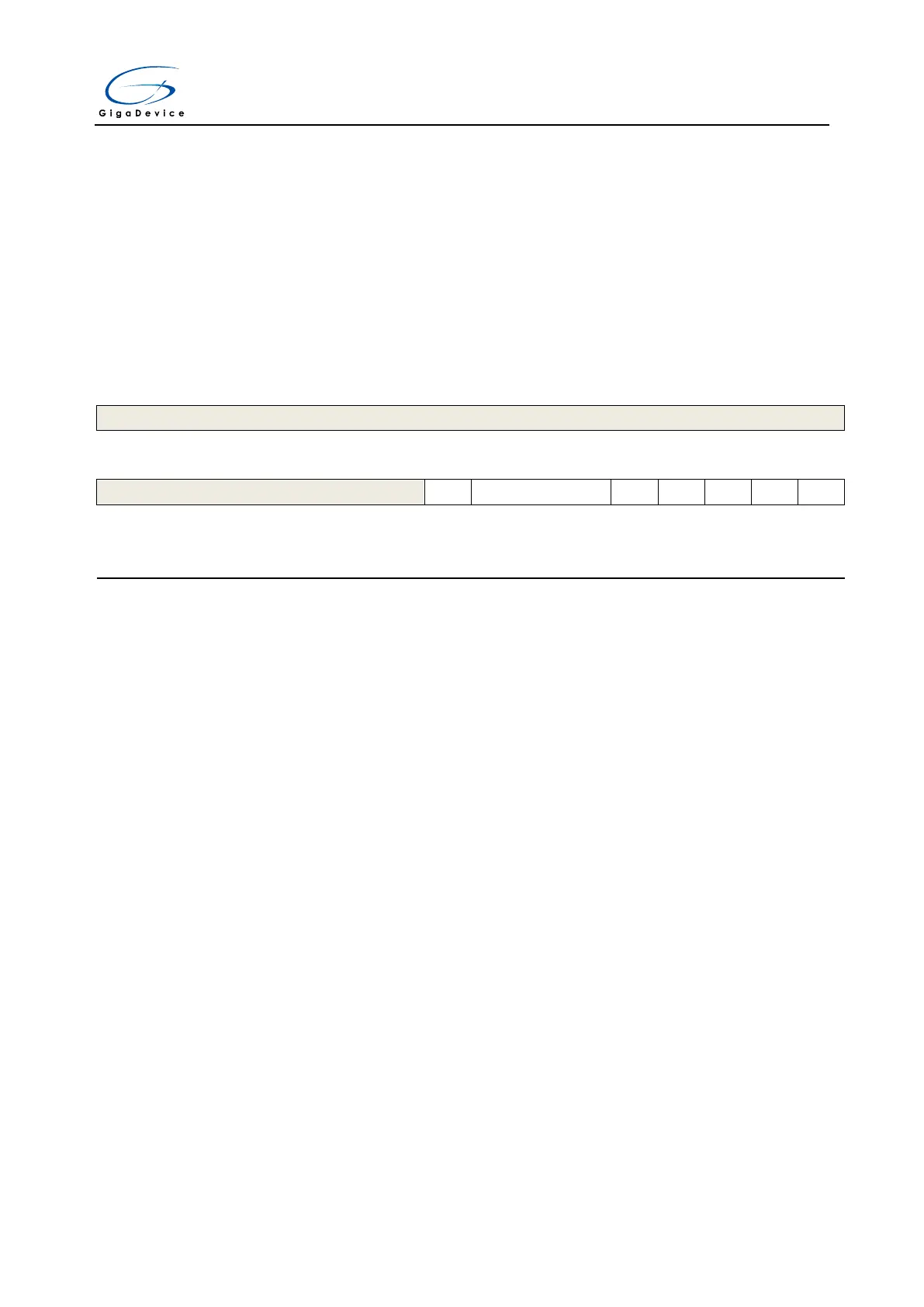
3.4. Register definition
PMU base address: 0x4000 7000
3.4.1. Control register (PMU_CTL)
Address offset: 0x00
Reset value: 0x0000 0000 (reset by wakeup from Standby mode)
This register can be accessed by half-word(16-bit) or word(32-bit)
Must be kept at reset value.
Backup Domain Write Enable
0: Disable write access to the registers in Backup domain
1: Enable write access to the registers in Backup domain
After reset, any write access to the registers in Backup domain is ignored. This bit
has to be set to enable write access to these registers.
Low Voltage Detector Threshold
000: 2.2V
001: 2.3V
010: 2.4V
011: 2.5V
100: 2.6V
101: 2.7V
110: 2.8V
111: 2.9V
Low Voltage Detector Enable
0: Disable Low Voltage Detector
1: Enable Low Voltage Detector
0: No effect
1: Reset the standby flag
This bit is always read as 0.

 Loading...
