GD32VF103 User Manual
394
Figure 18-18. I2S Phillips standard timing diagram (DTLEN=00, CHLEN=1, CKPL=0)
I2S_CK
I2S_SD
16-bit data
frame 1 (channel left) frame 2 (channel right)
MSB
I2S_WS
LSB
16-bit 0
MSB
Figure 18-19. I2S Phillips standard timing diagram (DTLEN=00, CHLEN=1, CKPL=1)
I2S_CK
I2S_SD
16-bit data
frame 1 (channel left) frame 2 (channel right)
MSB
I2S_WS
LSB
16-bit 0
MSB
When the packet type is 16-bit data packed in 32-bit frame, only one write or read operation
to or from the SPI_DATA register is needed to complete the transmission of a frame. The
remaining 16 bits are forced by hardware to 0x0000 to extend the data to 32-bit format.
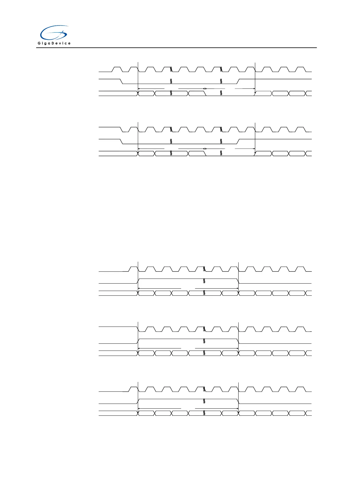
MSB justified standard
For MSB justified standard, I2S_WS and I2S_SD are updated on the falling edge of I2S_CK.
The SPI_DATA register is handled in the exactly same way as that for I2S Phillips standard.
The timing diagrams for each configuration are shown below.
Figure 18-20. MSB justified standard timing diagram (DTLEN=00, CHLEN=0, CKPL=0)
I2S_CK
I2S_SD
16-bit data
frame 1 (channel left) frame 2 (channel right)
MSB MSBLSB
I2S_WS
Figure 18-21. MSB justified standard timing diagram (DTLEN=00, CHLEN=0, CKPL=1)
I2S_CK
I2S_SD
16-bit data
frame 1 (channel left) frame 2 (channel right)
MSB MSBLSB
I2S_WS
Figure 18-22. MSB justified standard timing diagram (DTLEN=10, CHLEN=1, CKPL=0)
I2S_CK
I2S_SD
32-bit data
frame 1 (channel left) frame 2 (channel right)
MSB MSBLSB
I2S_WS



 To Next Page