GD32VF103 User Manual
166
example of the processing, from a raw 20-bit accumulated data to the final 16-bit result.
Figure 11-12. Numerical example with 5-bits shift and rounding
2 A C D 6Raw 20-bit data
19 15 11 7 3 0
1 5 6 6
15 11 7 3 0
Final result after 5-bit shift and rounding
to nearest
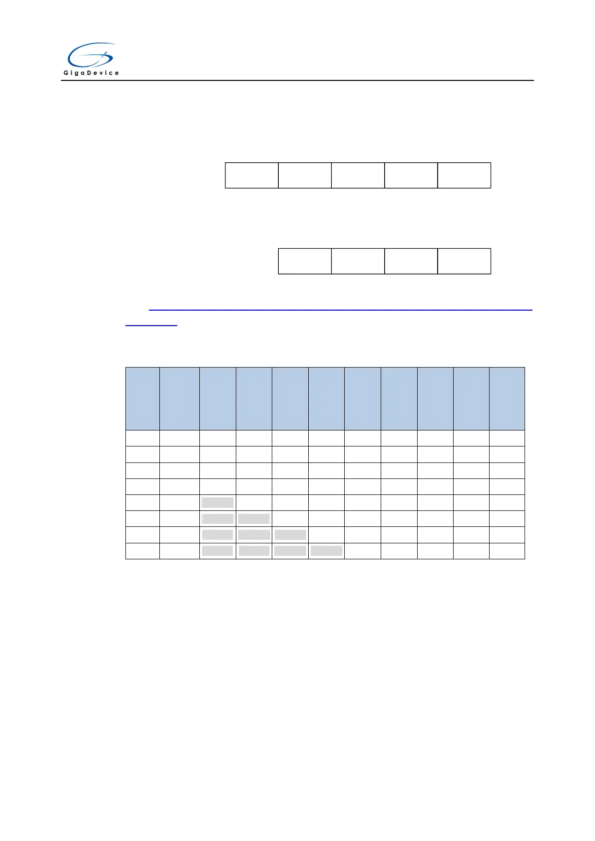
The Table 11-6. Maximum output results vs N and M (Grayed values indicates
truncation) below gives the data format for the various N and M combination, for a raw
conversion data equal to 0xFFF.
Table 11-6. Maximum output results vs N and M (Grayed values indicates truncation)
The conversion timings in oversampled mode do not change compared to standard
conversion mode: the sample time is maintained equal during the whole oversampling
sequence. New data are provided every N conversion, with an equivalent delay equal to:
N×t
ADC
=N×(t
SMPL
+t
CONV
) (11-2)
11.5. ADC sync mode
In devices with two ADC, ADC sync mode can be used.
In ADC sync mode, the conversion starts alternately or simultaneously triggered by ADC0
master to ADC1 slave, according to the mode selected by the SYNCM[3:0] bits in
ADC1_CTL0 register.