GD32VF103 User Manual
175
Cleared by software writing 0 to it or by reading the ADC_RDATA register.
Analog watchdog event flag
0: No analog watchdog event
1: Analog watchdog event
Set by hardware when the converted voltage crosses the values programmed in the
ADC_WDLT and ADC_WDHT registers. Cleared by software writing 0 to it.
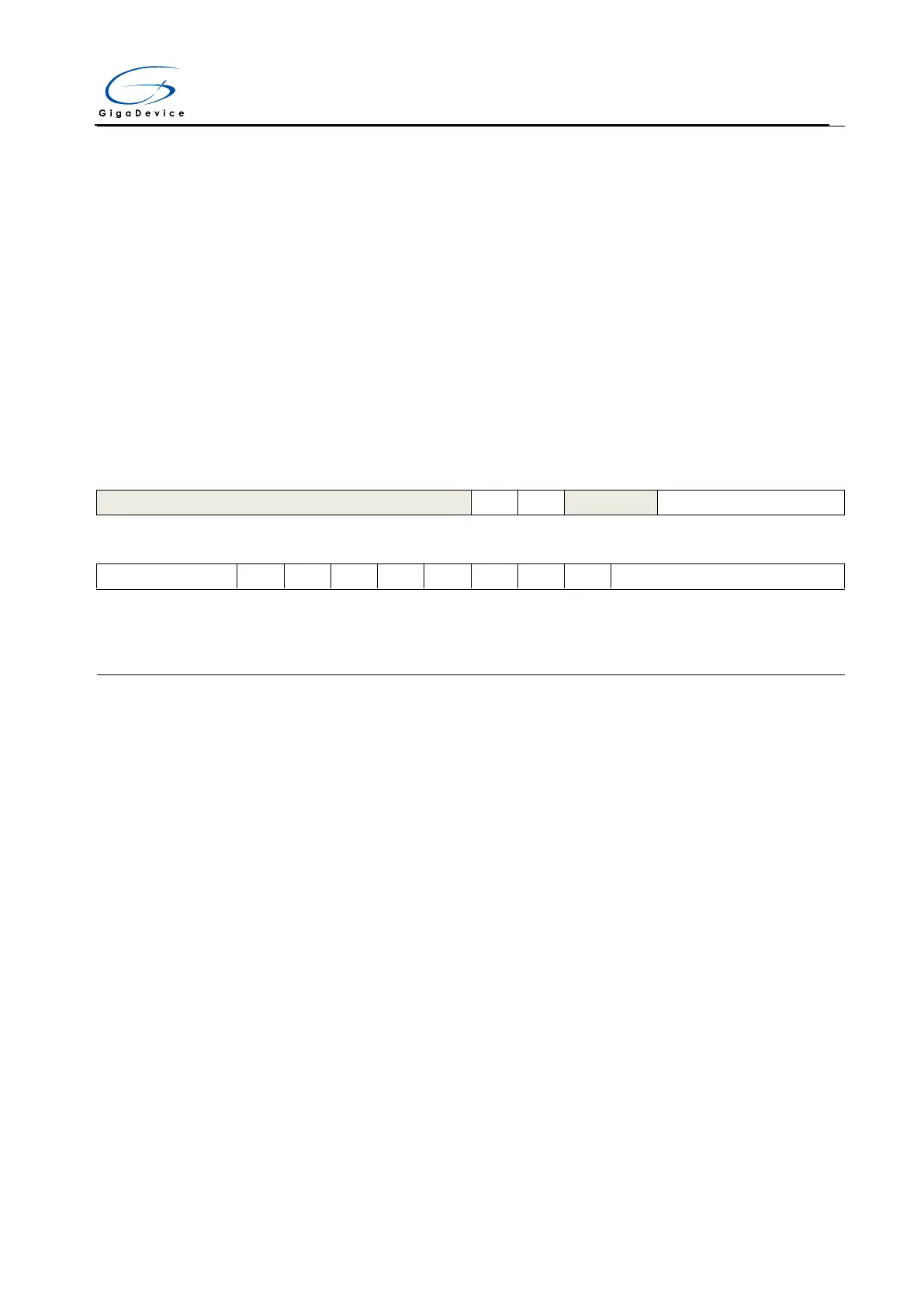
11.8.2. Control register 0 (ADC_CTL0)
Address offset: 0x04
Reset value: 0x0000 0000
This register has to be accessed by word(32-bit)
Must be kept at reset value
Regular channel analog watchdog enable
0: Regular channel analog watchdog disable
1: Regular channel analog watchdog enable
Inserted channel analog watchdog enable
0: Inserted channel analog watchdog disable
1: Inserted channel analog watchdog enable
Must be kept at reset value
These bits use to select the operating mode.
0000: Free mode.
0001: Combined regular parallel + inserted parallel mode
0010: Combined regular parallel + trigger rotation mode
0011: Combined inserted parallel + follow-up fast mode
0100: Combined inserted parallel + follow-up slow mode
0101: Inserted parallel mode only
0110: Regular parallel mode only
0111: Follow-up fast mode only
1000: Follow-up slow mode only



 To Next Page