GD32VF103 User Manual
97
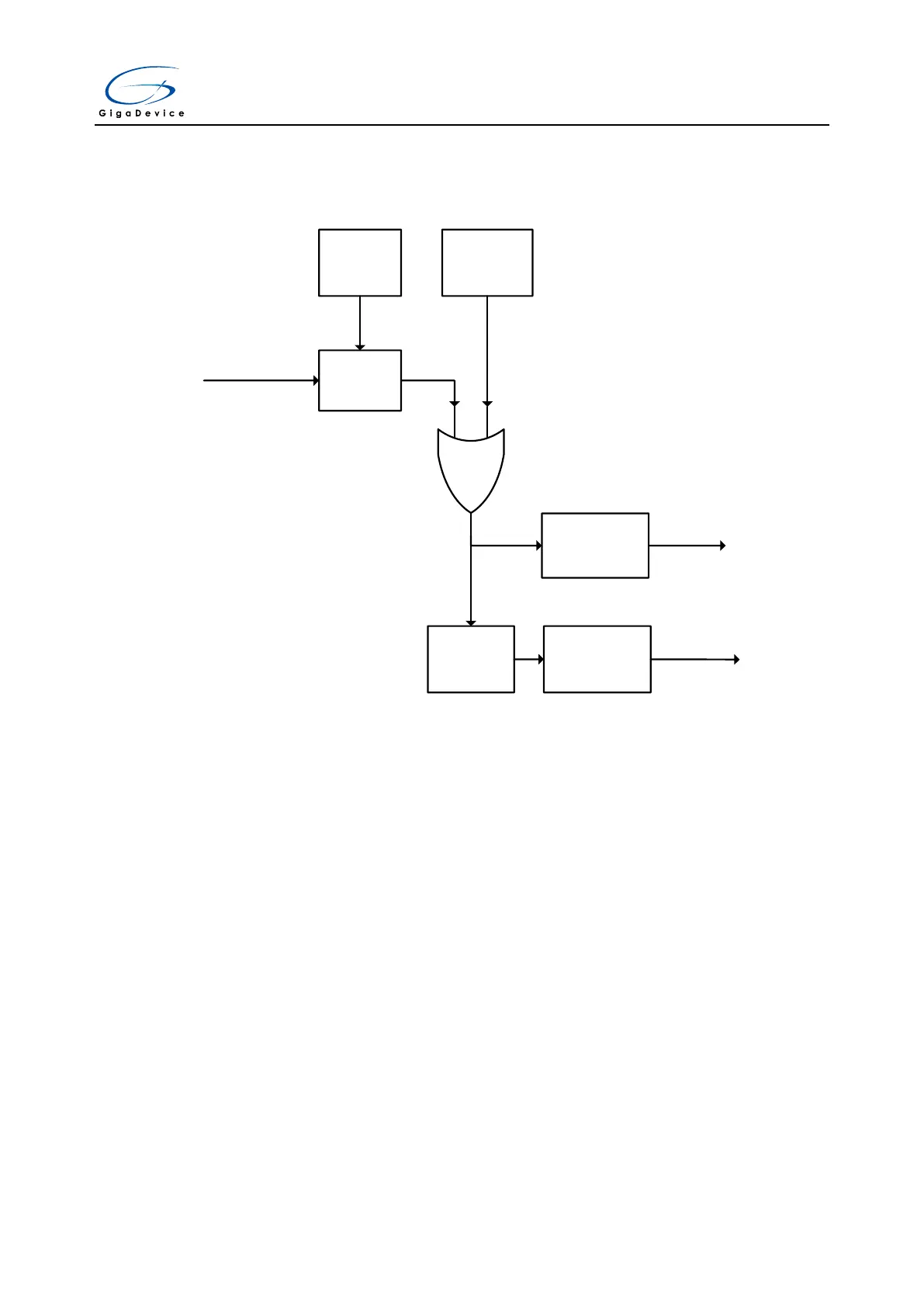
6.4. External interrupt and event (EXTI) block diagram
Figure 6-1. Block diagram of EXTI
EXTI Line0~18
Edge
detector
Polarity
Control
Software
Trigger
Interrupt Mask
Control
Event
Generate
Event Mask
Control
To ECLIC
To Wakeup Unit
6.5. External Interrupt and Event function overview
The EXTI contains up to 19 independent edge detectors and generates interrupts request or
event to the processer. The EXTI has three trigger types: rising edge, falling edge and both
edges. Each edge detector in the EXTI can be configured and masked independently.
The EXTI trigger source includes 16 external lines from GPIO pins and 3 lines from internal
modules (including LVD, RTC Alarm, USB Wakeup). All GPIO pins can be selected as an
EXTI trigger source by configuring AFIO_EXTISSx registers in GPIO module (please refer to
GPIO and AFIO section for detail).
EXTI can provide not only interrupts but also event signals to the processor. The RISC-V
processor fully implements the Wait For Interrupt (WFI), Wait For Event (WFE) and the Send
Event (SEV) instructions. EXTI can be used to wake up processor and the whole system
when some expected event occurs, such as a special GPIO pin toggling or RTC alarm.