GD32VF103 User Manual
161
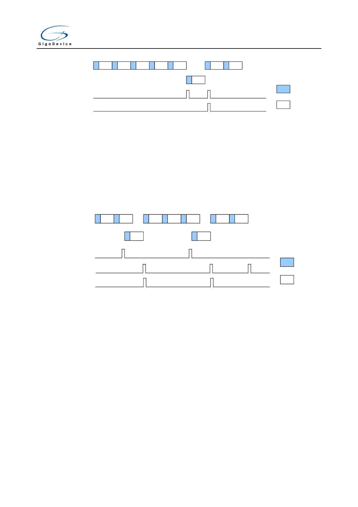
Figure 11-7. Auto-insertion, CNT = 1
CH0 CH1 CH2 CH3 CH4
Sample
Convert
· ·
·
CH15
EOIC
EOC
CH0 CH1
Regular
group
Inserted
group
The auto insertion mode cannot be enabled when the discontinuous conversion mode is set.
Triggered insertion
If the ICA bit is cleared, the triggered insertion occurs if a software or external trigger occurs
during the regular group channel conversion. In this situation, the ADC aborts from the current
conversion and starts the conversion of inserted channel sequence. After the inserted channel
group is done, the regular group channel conversion is resumed from the last aborted
conversion.
Figure 11-8. Triggered insertion
CH0 CH1 CH1 CH2 CH3 CH3 CH4
Inserted
trigger
Sample
Convert
· · ·
CH15 CH15
EOIC
EOC
Regular
group
Inserted
group
Analog watchdog
The analog watchdog is enabled when the RWDEN and IWDEN bits in the ADC_CTL0
register are set for regular and inserted channel groups respectively. When the analog voltage
converted by the ADC is below a low threshold or above a high threshold, the WDE bit in
ADC_STAT register will be set. An interrupt will be generated if the WDEIE bit is set. The
ADC_WDHT and ADC_WDLT registers are used to specify the high and low threshold. The
comparison is done before the alignment, so the threshold value is independent of the
alignment, which is specified by the DAL bit in the ADC_CTL1 register. One or more channels,
which are select by the RWDEN, IWDEN, WDSC and WDCHSEL[4:0] bits in ADC_CTL0
register, can be monitored by the analog watchdog.
11.4.7. Data alignment
The alignment of data stored after conversion can be specified by DAL bit in the ADC_CTL1
register.
After being decreased by the user-defined offset written in the ADC_IOFFx registers, the

 Loading...
