GD32VF103 User Manual
398
(DTLEN=01, CHLEN=1, CKPL=1)
I2S_CK
I2S_SD
24-bit data
MSB
I2S_WS
MSB
frame 1 frame 2
8-bit 0
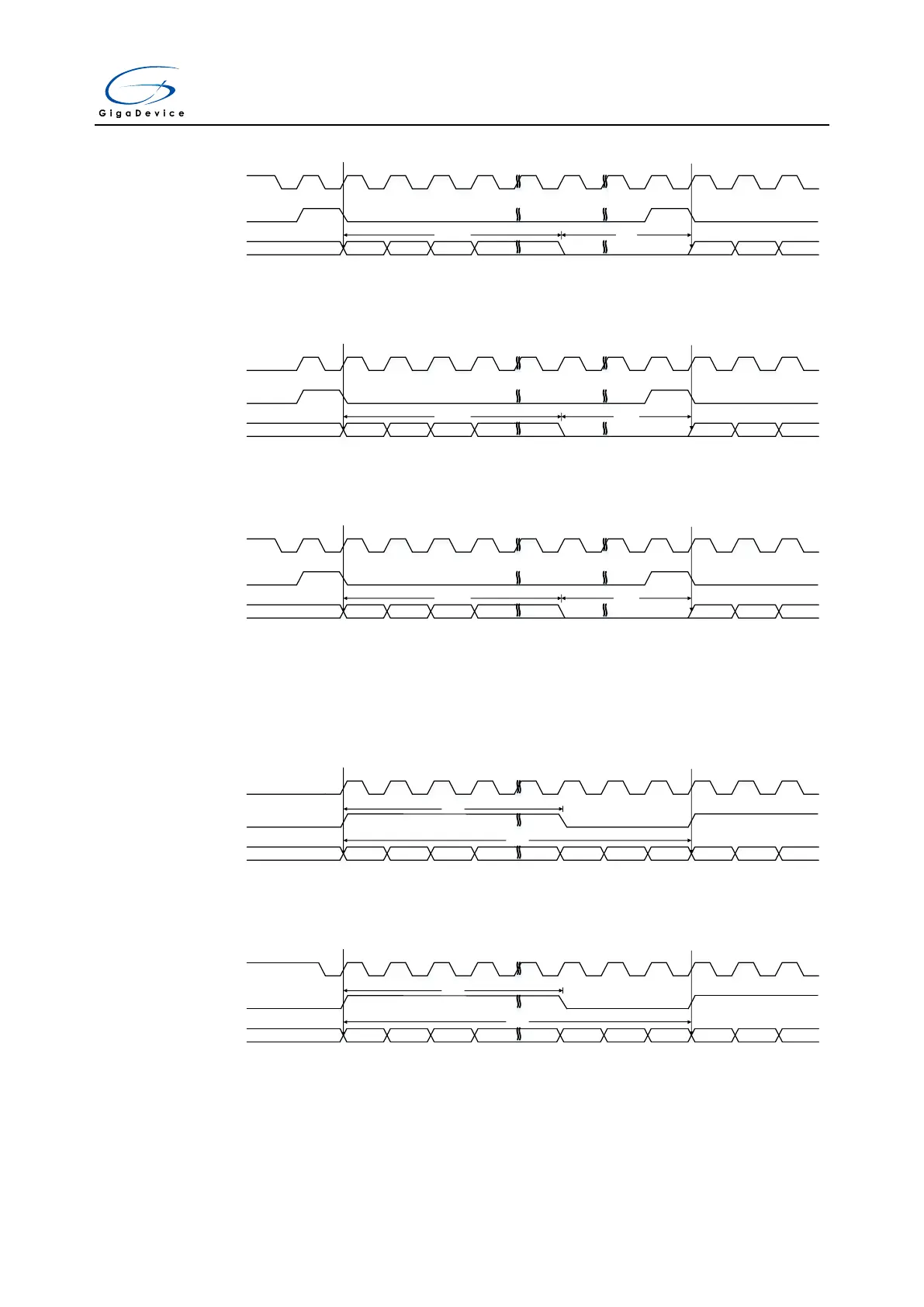
Figure 18-38. PCM standard short frame synchronization mode timing diagram
(DTLEN=00, CHLEN=1, CKPL=0)
I2S_CK
I2S_SD
16-bit data
MSB
I2S_WS
MSB
frame 1 frame 2
16-bit 0
Figure 18-39. PCM standard short frame synchronization mode timing diagram
(DTLEN=00, CHLEN=1, CKPL=1)
I2S_CK
I2S_SD
16-bit data
MSB
I2S_WS
MSB
frame 1 frame 2
16-bit 0
The timing diagrams for each configuration of the long frame synchronization mode are shown
below.
Figure 18-40. PCM standard long frame synchronization mode timing diagram
(DTLEN=00, CHLEN=0, CKPL=0)
I2S_CK
I2S_SD
16 bits
MSB
I2S_WS
MSB LSB
frame 1 frame 2
13 bits
Figure 18-41. PCM standard long frame synchronization mode timing diagram
(DTLEN=00, CHLEN=0, CKPL=1)
I2S_CK
I2S_SD
16 bits
MSB
I2S_WS
MSB LSB
frame 1 frame 2
13 bits
Figure 18-42. PCM standard long frame synchronization mode timing diagram



 To Next Page