GD32VF103 User Manual
50
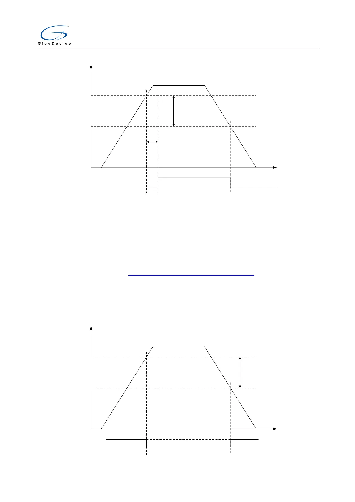
Figure 3-2. Waveform of the POR/PDR
VDD/VDDA
VPOR
tRSTTEMPO
2ms
Power Reset (Active Low)
t
VPDR
50mV
Vhyst
V
DDA
domain
The LVD is used to detect whether the V
DD
/V
DDA
supply voltage is lower than a programmed
threshold selected by the LVDT[2:0] bits in the Power control register(PMU_CTL). The LVD
is enabled by setting the LVDEN bit, and LVDF bit, which in the Power status register
(PMU_CS), indicates if V
DD
/V
DDA
is higher or lower than the LVD threshold. This event is
internally connected to the EXTI line 16 and can generate an interrupt if it is enabled through
the EXTI registers. Figure 3-3. Waveform of the LVD threshold shows the relationship
between the LVD threshold and the LVD output (LVD interrupt signal depends on EXTI line
16 rising or falling edge configuration). The following figure shows the relationship between
the supply voltage and the LVD signal. The hysteresis voltage (V
hyst
) is 100mV.
Figure 3-3. Waveform of the LVD threshold
VDD/VDDA
LVD output
t
LVD
threshold
100mV
Vhyst