GD32VF103 User Manual
393
to or from the SPI_DATA register is needed to complete the transmission of a frame.
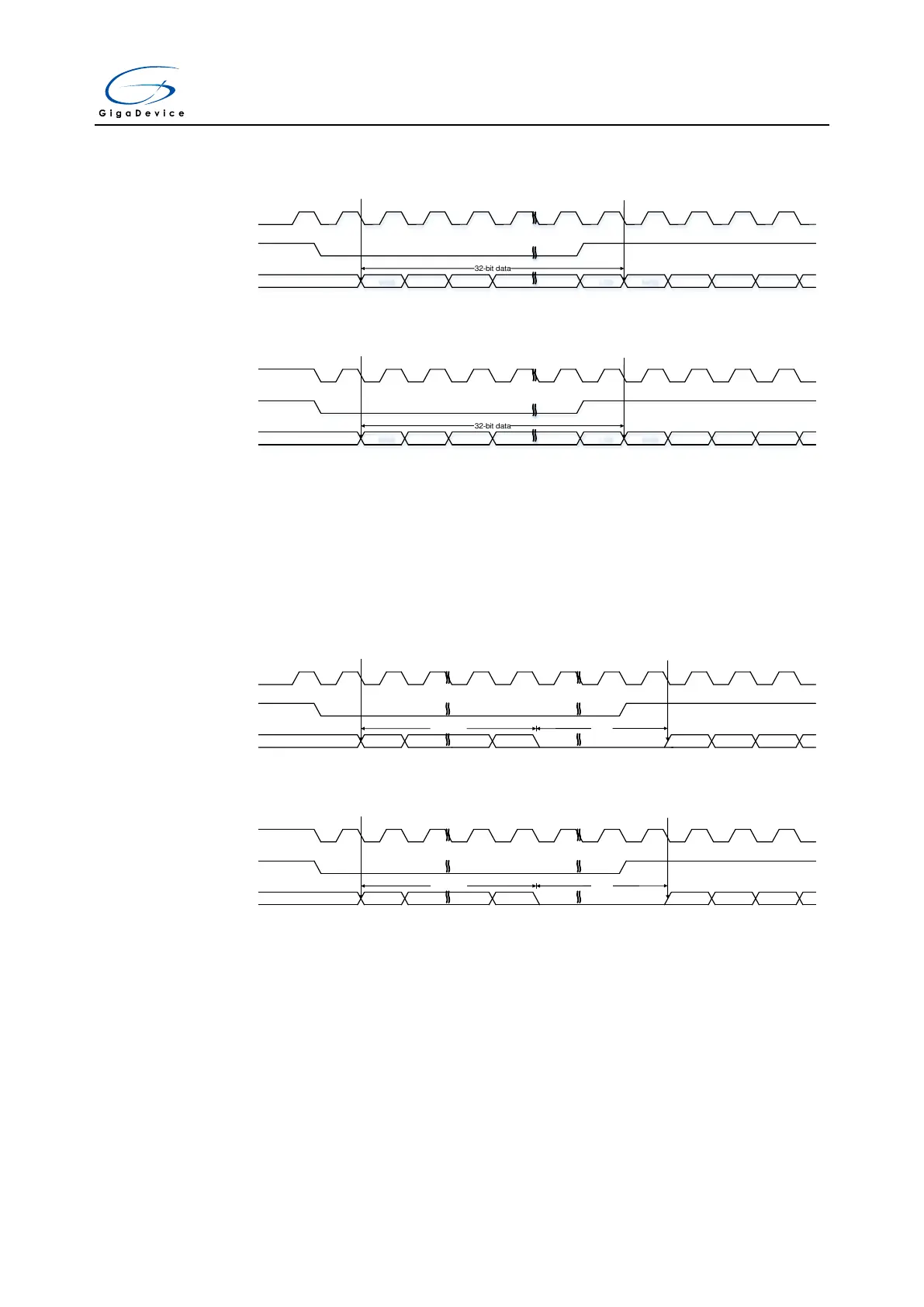
Figure 18-14. I2S Phillips standard timing diagram (DTLEN=10, CHLEN=1, CKPL=0)
I2S_CK
I2S_SD
32-bit data
frame 1 (channel left) frame 2 (channel right)
MSB MSBLSB
I2S_WS
Figure 18-15. I2S Phillips standard timing diagram (DTLEN=10, CHLEN=1, CKPL=1)
I2S_CK
I2S_SD
32-bit data
frame 1 (channel left) frame 2 (channel right)
MSB MSBLSB
I2S_WS
When the packet type is 32-bit data packed in 32-bit frame, two write or read operations to or
from the SPI_DATA register are needed to complete the transmission of a frame. In
transmission mode, if a 32-bit data is going to be sent, the first data written to the SPI_DATA
register should be the higher 16 bits, and the second one should be the lower 16 bits. In
reception mode, if a 32-bit data is received, the first data read from the SPI_DATA register
should be the higher 16 bits, and the second one should be the lower 16 bits.
Figure 18-16. I2S Phillips standard timing diagram (DTLEN=01, CHLEN=1, CKPL=0)
I2S_CK
I2S_SD
24-bit data
frame 1 (channel left) frame 2 (channel right)
MSB
I2S_WS
LSB
8-bit 0
MSB
Figure 18-17. I2S Phillips standard timing diagram (DTLEN=01, CHLEN=1, CKPL=1)
I2S_CK
I2S_SD
24-bit data
frame 1 (channel left)
frame 2 (channel
right)
MSB
I2S_WS
LSB
8-bit 0
MSB
When the packet type is 24-bit data packed in 32-bit frame, two write or read operations to
or from the SPI_DATA register are needed to complete the transmission of a frame. In
transmission mode, if a 24-bit data D[23:0] is going to be sent, the first data written to the
SPI_DATA register should be the higher 16 bits D[23:8]. And the second one should be a
16-bit data, the higher 8 bits of this 16-bit data should be D[7:0] and the lower 8 bits can be
any value. In reception mode, if a 24-bit data D[23:0] is received, the first data read from the
SPI_DATA register is D[23:8]. And the second one is a 16-bit data, the higher 8 bits of this
16-bit data are D[7:0] and the lower 8 bits are zeros.



 To Next Page