GD32VF103 User Manual
400
18.9.2. I2S clock
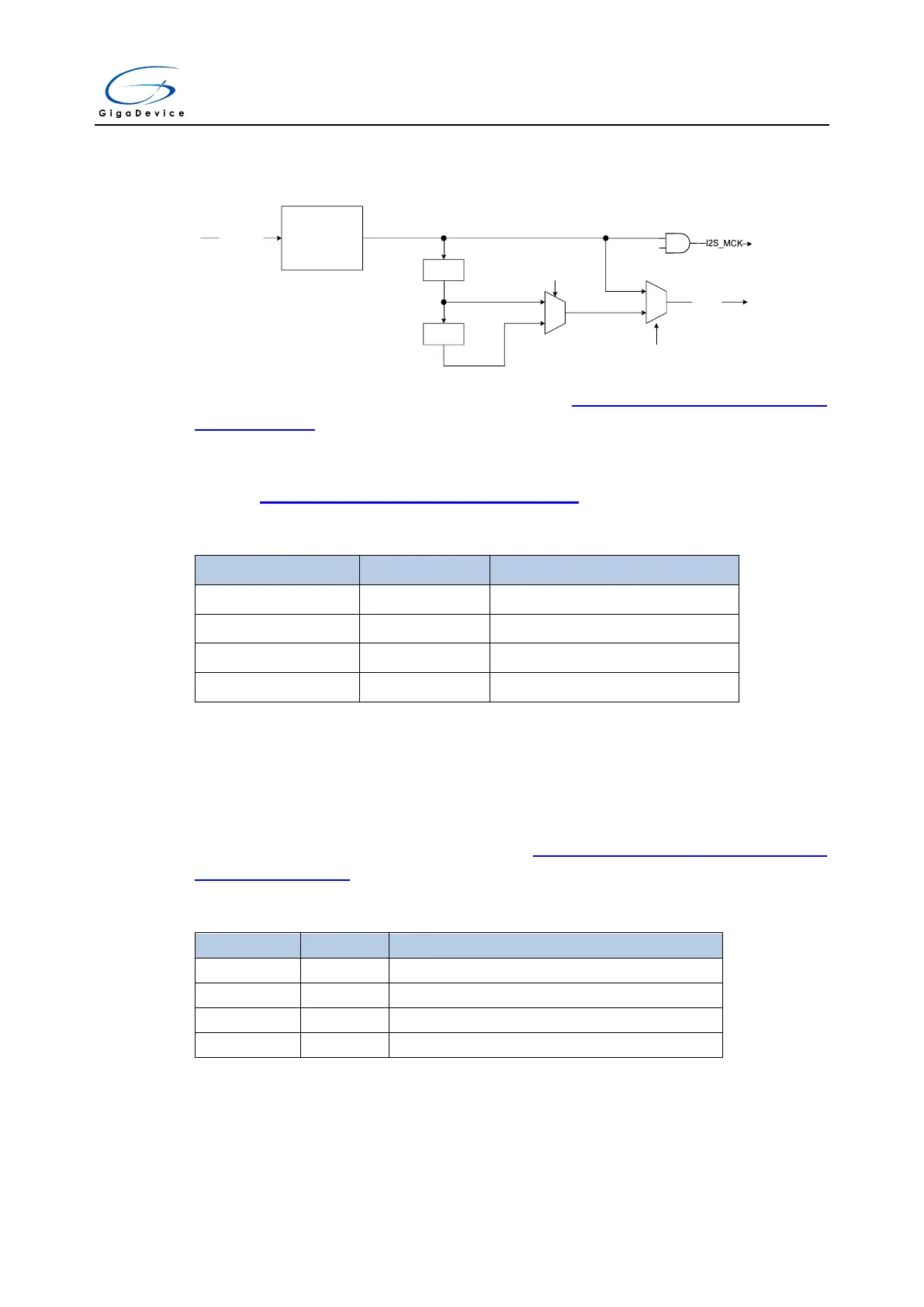
Figure 18-48. Block diagram of I2S clock generator
8-bit
Configurable
Divider
I2SCLK
frequency dividing ratio =
DIV * 2 + OF
DIV4
DIV2
1
0
CHLEN
0
1
MCKOEN
I2S_CK
MCKOEN
The block diagram of I2S clock generator is shown as Figure 18-48. Block diagram of I2S
clock generator. The I2S interface clocks are configured by the DIV bits, the OF bit, the
MCKOEN bit in the SPI_I2SPSC register and the CHLEN bit in the SPI_I2SCTL register. The
source clock is the system clock(CK_SYS). The I2S bitrate can be calculated by the formulas
shown in Table 18-4. I2S bitrate calculation formulas.
Table 18-4. I2S bitrate calculation formulas
I2SCLK / (8 * (DIV * 2 + OF))
I2SCLK / (4 * (DIV * 2 + OF))
The relationship between audio sampling frequency (Fs) and I2S bitrate is defined by the
following formula:
Fs = I2S bitrate / (number of bits per channel * number of channels)
So, in order to get the desired audio sampling frequency, the clock generator needs to be
configured according to the formulas listed in Table 18-5. Audio sampling frequency
calculation formulas.
Table 18-5. Audio sampling frequency calculation formulas
I2SCLK / (32 * (DIV * 2 + OF))
I2SCLK / (64 * (DIV * 2 + OF))
I2SCLK / (256 * (DIV * 2 + OF))
I2SCLK / (256 * (DIV * 2 + OF))



 To Next Page