GD32VF103 User Manual
191
12.3.6. DAC noise wave
There are two methods of adding noise wave to the DAC output data: LFSR noise wave and
Triangle wave. The noise wave mode can be selected by the DWMx bits in the DAC_CTL
register. The amplitude of the noise can be configured by the DAC noise wave bit width
(DWBWx) bits in the DAC_CTL register.
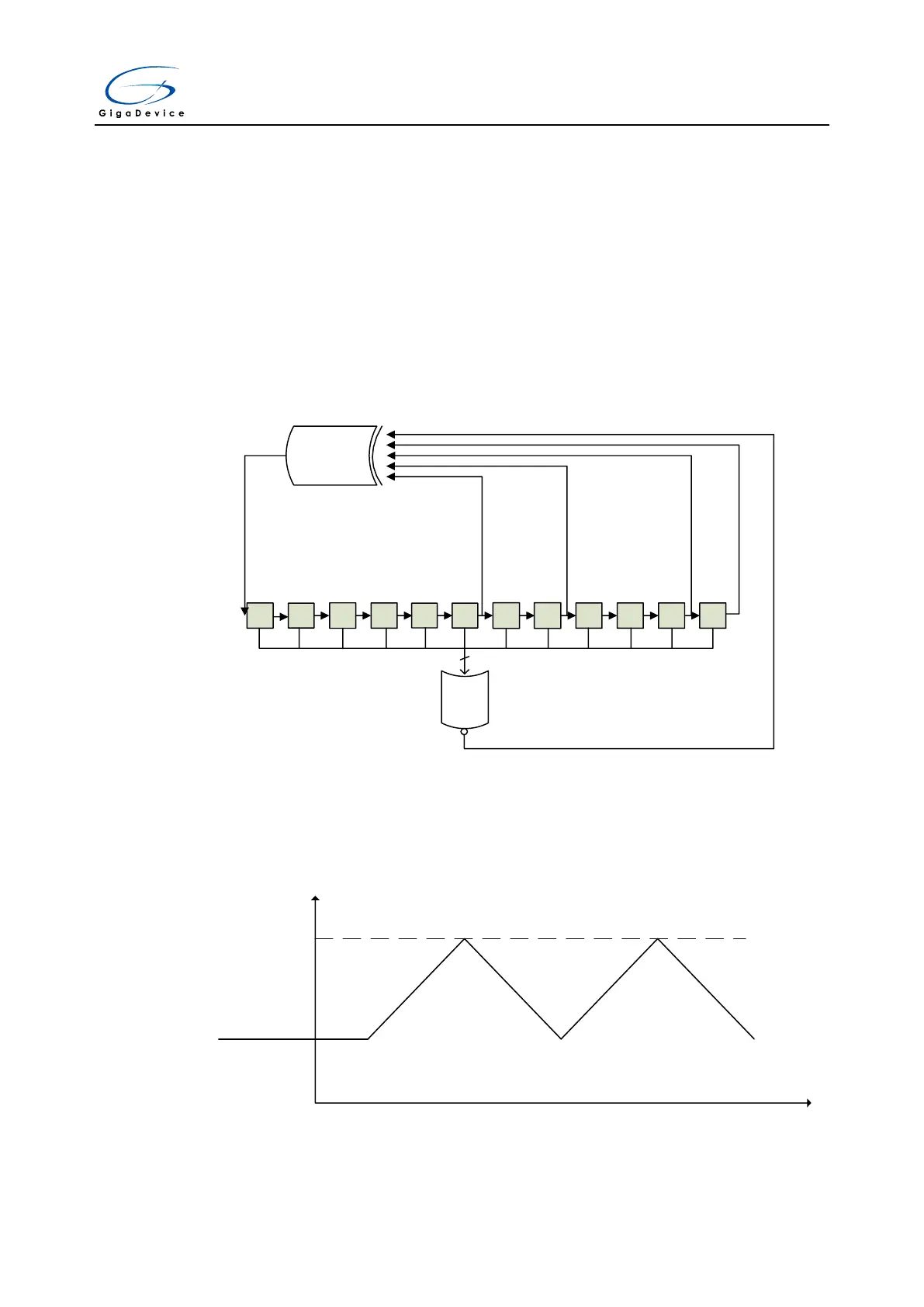
LFSR noise wave mode: there is a Linear Feedback Shift Register (LFSR) in the DAC control
logic, it controls the LFSR noise signal which is added to the DACx_DH value. When the
configured DAC noise wave bit width is less than 12, the noise signal equals to the LSB
DWBWx bits of the LFSR register, while the MSB bits are masked.
Figure 12-2. DAC LFSR algorithm
9
7
8
6 5 4 3 2 1
11
10
0
X
6
X
0
X
4
X
XOR
X
12
NOR
12
Triangle noise mode: in this mode, a triangle signal is added to the DACx_DH value. The
minimum value of the triangle signal is 0, while the maximum value of the triangle signal is
(2<<DWBWx)-1.
Figure 12-3. DAC triangle noise wave
(2<<DWBWx)-1 +
DACx_DH value
DACx_DH value