GD32VF103 User Manual
282
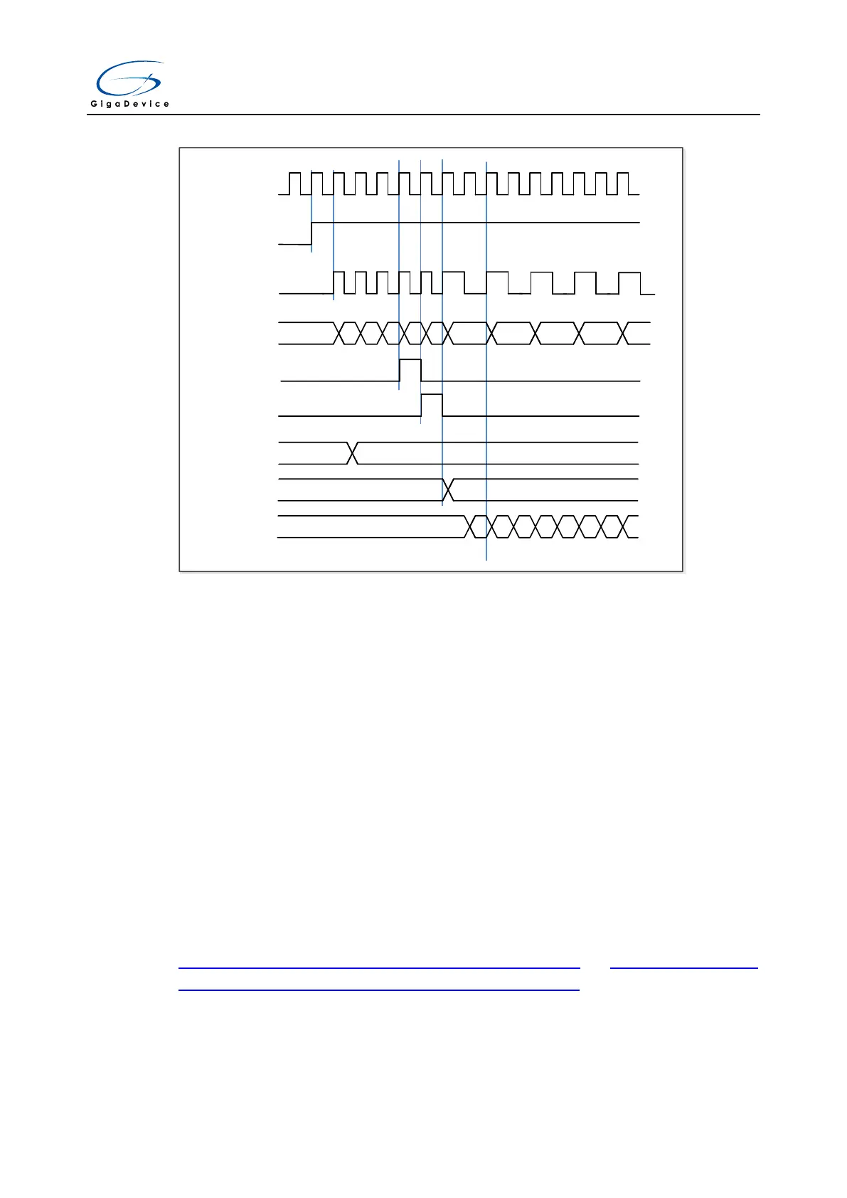
Figure 15-36. Counter timing diagram with prescaler division change from 1 to 2
TIMER_CK
CEN
PSC_CLK
CNT_REG
Reload Pulse
Prescaler CNT
Prescaler BUF
F7 F8 F9 FA FB FC 01 02 03
0
1
0 1
0 1
0 1
0 1
0 1
PSC value
0 04
UPG
0
Up counting mode
In this mode, the counter counts up continuously from 0 to the counter reload value, which is
defined in the TIMERx_CAR register, in a count-up direction. Once the counter reaches the
counter reload value, the counter restarts from 0. If the repetition counter is set, the update
event will be generated after (TIMERx_CREP+1) times of overflow. Otherwise the update
event is generated each time when counter overflows. The counting direction bit DIR in the
TIMERx_CTL0 register should be set to 0 for the up counting mode.
Whenever, if the update event software trigger is enabled by setting the UPG bit in the
TIMERx_SWEVG register, the counter value will be initialized to 0 and an update event will
be generated.
If the UPDIS bit in TIMERx_CTL0 register is set, the update event is disabled.
When an update event occurs, all the registers (auto reload register, prescaler register) are
updated.
Figure 15-37. Timing chart of up counting mode, PSC=0/1 and Figure 15-38. Timing
chart of up counting mode, change TIMERx_CAR ongoing show some examples of the
counter behavior for different clock prescaler factors when TIMERx_CAR=0x63.