formed by the ring links of ERP2 and the ring link between the interconnection
nodes that is controlled by ERP1. ERP2 is a sub-ring. Ring node A is the RPL owner
node for ERP1, and ring node E is the RPL owner node for ERP2. These ring nodes (A
and E) are responsible for blocking the traffic channel on the RPL for ERP1 and ERP2
respectively. There is no restriction on which ring link on an ring may be set as the
RPL. For example the RPL of ERP1 could be set as the link between ring node C and
D.
Ring nodes C and D, that are common to both ERP1 and ERP2, are called
interconnection nodes. The ring link between the interconnection nodes are
controlled and protected by the ring it belongs to. In the example for the Normal
Condition, the ring link between ring nodes C and D is part of ERP1, and, as such,
are controlled and protected by ERP1. Ethernet characteristic information traffic
corresponding to the traffic channel may be transferred over a common Ethernet
connection for ERP1 and ERP2 through the interconnection nodes C and D.
Interconnection nodes C and D have separate ERP Control Processes for each
Ethernet Ring.
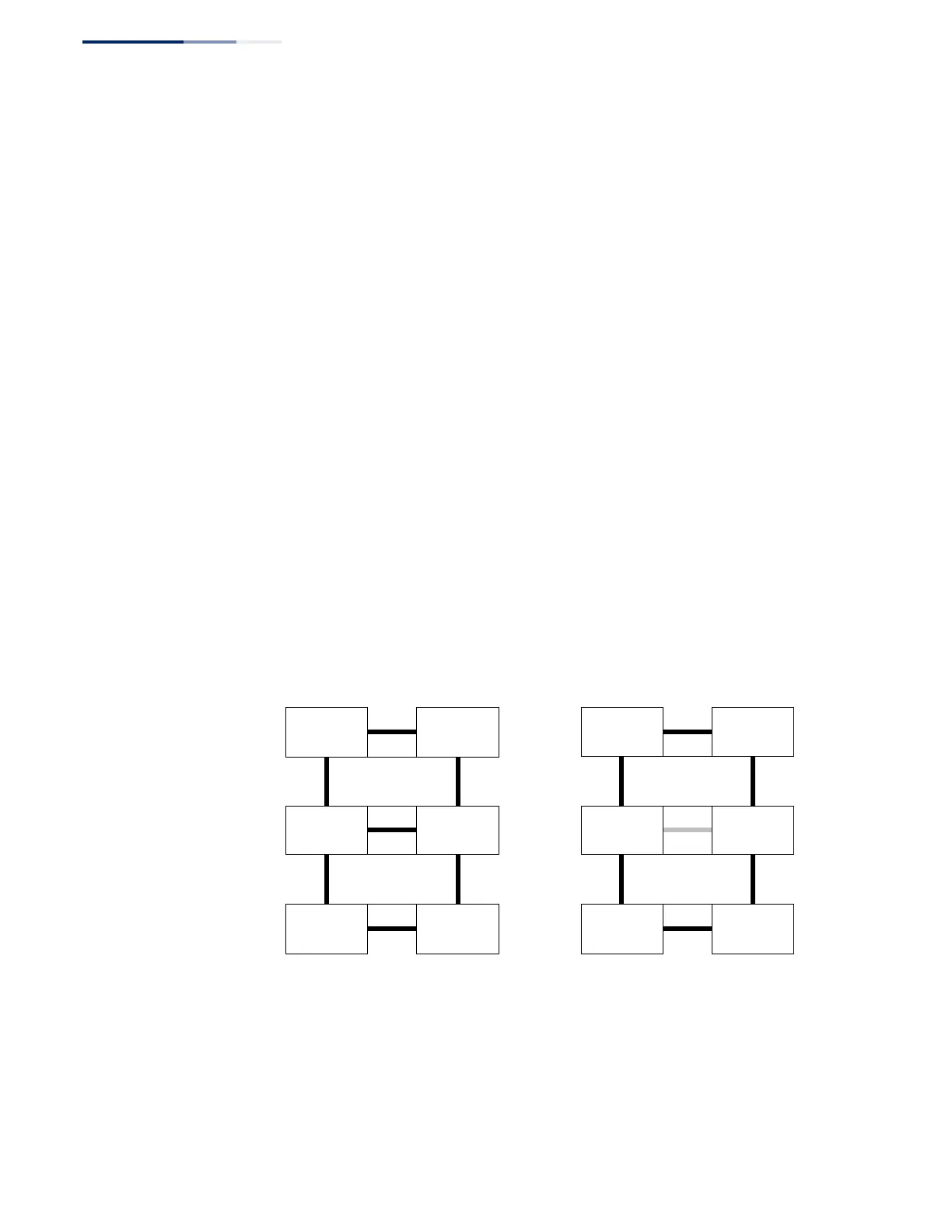
Figure 268 on page 410 (Signal Fail Condition) illustrates a situation where
protection switching has occurred due to an SF condition on the ring link between
interconnection nodes C and D. The failure of this ring link triggers protection only
on the ring to which it belongs, in this case ERP1. The traffic and R-APS channels are
blocked bi-directionally on the ports where the failure is detected and bi-
directionally unblocked at the RPL connection point on ERP1. The traffic channels
remain bi-directionally blocked at the RPL connection point on ERP2. This prevents
the formation of a loop.
Figure 268: Ring Interconnection Architecture (Multi-ring/Ladder Network)
Normal Condition Signal Fail Condition
RPL Owner
Node
for ERP1
RPL Owner
Node
for ERP2
RPL Owner
Node
for ERP1
RPL Owner
Node
for ERP2
Configuration Guidelines for ERPS
1.
Create an ERPS ring (Configure Domain – Add): The ring name is used as an
index in the G.8032 database.
2.
Configure the east and west interfaces (Configure Domain – Configure Details):
Each node on the ring connects to it through two ring ports. Configure one