Home
LevelOne
Switch
GEL-5261
Page 392 (Figure 248: Configuring an RMON Alarm)
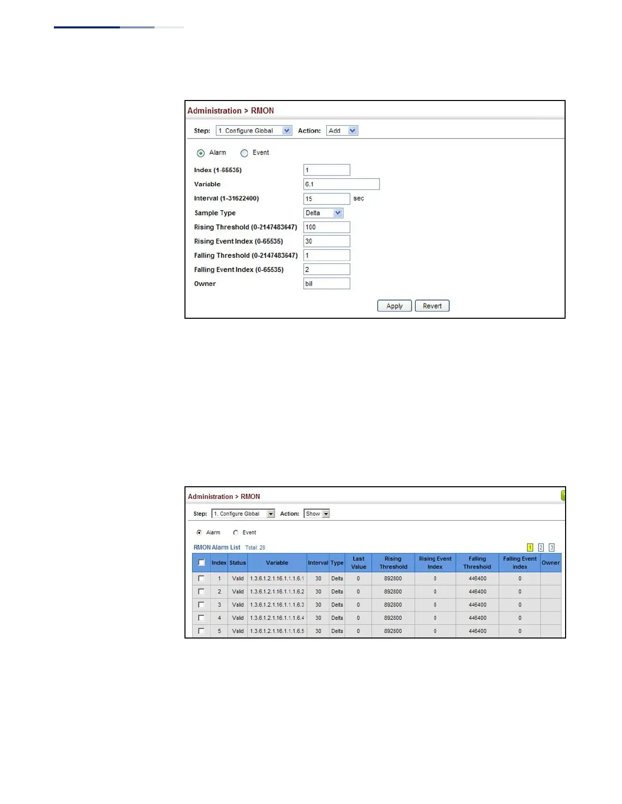
LevelOne GEL-5261 - Figure 248: Configuring an RMON Alarm; Figure 249: Showing Configured RMON Alarms
570 pages
Manual
Save Page as PDF
To Next Page
To Next Page
To Previous Page
To Previous Page
Loading...
Chapter 13
|
Basic Administr
ation Protocols
Remote Monitoring
–
392
–
Figure
248:
Config
uring a
n RMON
Alar
m
To show configu
red RMON alarms
:
1.
Click Administrati
on,
RMON.
2.
Select Configure Glob
al from th
e Step
list.
3.
Select Show from
the Action
list.
4.
Click Al
arm.
Figure
249:
Showi
ng Con
figure
d RMON
Alar
ms
391
393
Table of Contents
Main Page
Default Chapter
1
Default Chapter
1
User Manual
1
How to Use this Guide
3
Table of Contents
5
Contents
5
Figures
15
Tables
27
Getting Started
29
1 Introduction
31
Key Features
31
Table 1: Key Features
31
Description of Software Features
33
Address Resolution Protocol
37
System Defaults
38
Table 2: System Defaults
38
Web Configuration
41
2 Using the Web Interface
43
Connecting to the Web Interface
43
Navigating the Web Browser Interface
44
Dashboard
44
Figure 1: Dashboard
45
Configuration Options
46
Panel Display
46
Table 3: Web Page Configuration Buttons
46
Main Menu
47
Table 4: Switch Main Menu
47
3 Basic Management Tasks
63
Displaying System Information
64
Figure 2: System Information
64
Displaying Hardware/Software Versions
65
Configuring Support for Jumbo Frames
66
Figure 3: General Switch Information
66
Displaying Bridge Extension Capabilities
67
Figure 4: Configuring Support for Jumbo Frames
67
Figure 5: Displaying Bridge Extension Configuration
68
Managing System Files
69
Copying Files Via FTP/SFTP/TFTP or HTTP
69
Saving the Running Configuration to a Local File
71
Figure 6: Copy Firmware
71
Setting the Start-Up File
72
Figure 7: Saving the Running Configuration
72
Figure 8: Setting Start-Up Files
72
Showing System Files
73
Automatic Operation Code Upgrade
73
Figure 9: Displaying System Files
73
Setting the System Clock
77
Figure 10: Configuring Automatic Code Upgrade
77
Figure 11: Manually Setting the System Clock
78
Setting the Time Manually
78
Configuring NTP
79
Figure 12: Setting the Polling Interval for SNTP
79
Setting the SNTP Polling Interval
79
Configuring Time Servers
80
Figure 13: Configuring NTP
80
Figure 14: Specifying SNTP Time Servers
81
Figure 15: Adding an NTP Time Server
82
Figure 16: Showing the NTP Time Server List
82
Figure 17: Adding an NTP Authentication Key
83
Figure 18: Showing the NTP Authentication Key List
84
Setting the Time Zone
84
Configuring Summer Time
85
Figure 19: Setting the Time Zone
85
Table 5: Predefined Summer-Time Parameters
86
Configuring the Console Port
87
Figure 20: Configuring Summer Time
87
Figure 21: Console Port Settings
88
Configuring Telnet Settings
89
Displaying CPU Utilization
90
Figure 22: Telnet Connection Settings
90
Configuring CPU Guard
91
Figure 23: Displaying CPU Utilization
91
Displaying Memory Utilization
92
Figure 24: Configuring CPU Guard
92
Resetting the System
93
Figure 25: Displaying Memory Utilization
93
Figure 26: Restarting the Switch (Immediately)
95
Figure 27: Restarting the Switch (In)
95
Figure 28: Restarting the Switch (At)
96
Figure 29: Restarting the Switch (Regularly)
96
4 Interface Configuration
97
Port Configuration
98
Configuring by Port List
98
Configuring by Port Range
100
Figure 30: Configuring Connections by Port List
100
Displaying Connection Status
101
Figure 31: Configuring Connections by Port Range
101
Showing Port or Trunk Statistics
102
Figure 32: Displaying Port Information
102
Table 6: Port Statistics
102
Figure 33: Showing Port Statistics (Table)
105
Displaying Statistical History
106
Figure 34: Showing Port Statistics (Chart)
106
Figure 35: Configuring a History Sample
108
Figure 36: Showing Entries for History Sampling
108
Figure 37: Showing Status of Statistical History Sample
109
Figure 38: Showing Current Statistics for a History Sample
109
Displaying Transceiver Data
110
Figure 39: Showing Ingress Statistics for a History Sample
110
Configuring Transceiver Thresholds
111
Figure 40: Displaying Transceiver Data
111
Performing Cable Diagnostics
113
Figure 41: Configuring Transceiver Thresholds
113
Trunk Configuration
115
Figure 42: Performing Cable Tests
115
Configuring a Static Trunk
116
Figure 43: Configuring Static Trunks
116
Figure 44: Creating Static Trunks
117
Figure 45: Adding Static Trunks Members
118
Figure 46: Configuring Connection Parameters for a Static Trunk
118
Configuring a Dynamic Trunk
119
Figure 47: Showing Information for Static Trunks
119
Figure 48: Configuring Dynamic Trunks
119
Figure 49: Configuring the LACP Aggregator Admin Key
122
Figure 50: Enabling LACP on a Port
123
Figure 51: Configuring LACP Parameters on a Port
123
Figure 52: Showing Members of a Dynamic Trunk
124
Figure 53: Configuring Connection Settings for a Dynamic Trunk
124
Displaying LACP Port Counters
125
Figure 54: Showing Connection Parameters for Dynamic Trunks
125
Table 7: LACP Port Counters
125
Displaying LACP Settings and Status for the Local Side
126
Figure 55: Displaying LACP Port Counters
126
Table 8: LACP Internal Configuration Information
126
Figure 56: Displaying LACP Port Internal Information
127
Displaying LACP Settings and Status for the Remote Side
128
Table 9: LACP Remote Device Configuration Information
128
Configuring Load Balancing
129
Figure 57: Displaying LACP Port Remote Information
129
Figure 58: Configuring Load Balancing
130
Saving Power
131
Configuring Local Port Mirroring
132
Figure 59: Enabling Power Savings
132
Figure 60: Configuring Local Port Mirroring
132
Figure 61: Configuring Local Port Mirroring
133
Configuring Remote Port Mirroring
134
Figure 62: Displaying Local Port Mirror Sessions
134
Figure 63: Configuring Remote Port Mirroring
134
Figure 64: Configuring Remote Port Mirroring (Source)
137
Sampling Traffic Flows
138
Figure 65: Configuring Remote Port Mirroring (Intermediate)
138
Figure 66: Configuring Remote Port Mirroring (Destination)
138
Configuring Sflow Receiver Settings
139
Figure 67: Configuring an Sflow Receiver
140
Configuring an Sflow Polling Instance
141
Figure 68: Showing Sflow Receivers
141
Figure 69: Configuring an Sflow Instance
142
Figure 70: Showing Sflow Instances
142
Traffic Segmentation
143
Enabling Traffic Segmentation
143
Configuring Uplink and Downlink Ports
144
Figure 71: Enabling Traffic Segmentation
144
Table 10: Traffic Segmentation Forwarding
144
Figure 72: Configuring Members for Traffic Segmentation
145
Figure 73: Showing Traffic Segmentation Members
146
5 VLAN Configuration
147
IEEE 802.1Q Vlans
147
Figure 74: VLAN Compliant and VLAN Non-Compliant Devices
148
Configuring VLAN Groups
149
Figure 75: Creating Static Vlans
151
Figure 76: Modifying Settings for Static Vlans
151
Adding Static Members to Vlans
152
Figure 77: Showing Static Vlans
152
Figure 78: Configuring Static Members by VLAN Index
154
Figure 79: Configuring Static VLAN Members by Interface
155
IEEE 802.1Q Tunneling
156
Figure 80: Configuring Static VLAN Members by Interface Range
156
Figure 81: Qinq Operational Concept
157
Enabling Qinq Tunneling on the Switch
160
Creating CVLAN to SPVLAN Mapping Entries
161
Figure 82: Enabling Qinq Tunneling
161
Figure 83: Configuring CVLAN to SPVLAN Mapping Entries
162
Figure 84: Showing CVLAN to SPVLAN Mapping Entries
162
Adding an Interface to a Qinq Tunnel
163
Protocol Vlans
164
Figure 85: Adding an Interface to a Qinq Tunnel
164
Configuring Protocol VLAN Groups
165
Figure 86: Configuring Protocol Vlans
166
Figure 87: Displaying Protocol Vlans
166
Mapping Protocol Groups to Interfaces
166
Configuring MAC-Based Vlans
168
Figure 88: Assigning Interfaces to Protocol Vlans
168
Figure 89: Showing the Interface to Protocol Group Mapping
168
Figure 90: Configuring MAC-Based Vlans
170
Figure 91: Showing MAC-Based Vlans
170
6 Address Table Settings
171
Displaying the Dynamic Address Table
171
Clearing the Dynamic Address Table
172
Figure 92: Displaying the Dynamic MAC Address Table
172
Changing the Aging Time
173
Figure 93: Clearing Entries in the Dynamic MAC Address Table
173
Configuring MAC Address Learning
174
Figure 94: Setting the Address Aging Time
174
Figure 95: Configuring MAC Address Learning
175
Setting Static Addresses
176
Figure 96: Configuring Static MAC Addresses
177
Figure 97: Displaying Static MAC Addresses
177
Issuing MAC Address Traps
178
Figure 98: Issuing MAC Address Traps (Global Configuration)
178
Figure 99: Issuing MAC Address Traps (Interface Configuration)
179
7 Spanning Tree Algorithm
181
Overview
181
Figure 100: STP Root Ports and Designated Ports
182
Figure 101: MSTP Region, Internal Spanning Tree, Multiple Spanning Tree
182
Configuring Loopback Detection
183
Figure 102: Spanning Tree - Common Internal, Common, Internal
183
Configuring Global Settings for STA
185
Figure 103: Configuring Port Loopback Detection
185
Figure 104: Configuring Global Settings for STA (STP)
189
Figure 105: Configuring Global Settings for STA (RSTP)
189
Displaying Global Settings for STA
190
Figure 106: Configuring Global Settings for STA (MSTP)
190
Configuring Interface Settings for STA
191
Figure 107: Displaying Global Settings for STA
191
Table 11: Recommended STA Path Cost Range
192
Table 12: Default STA Path Costs
192
Figure 108: Determining the Root Port
193
Displaying Interface Settings for STA
196
Figure 109: Configuring Interface Settings for STA
196
Figure 110: STA Port Roles
197
Figure 111: Displaying Interface Settings for STA
198
Configuring Multiple Spanning Trees
199
Figure 112: Creating an MST Instance
200
Figure 113: Displaying MST Instances
200
Figure 114: Modifying the Priority for an MST Instance
201
Figure 115: Displaying Global Settings for an MST Instance
201
Figure 116: Adding a VLAN to an MST Instance
202
Figure 117: Displaying Members of an MST Instance
202
Configuring Interface Settings for MSTP
203
Figure 118: Configuring MSTP Interface Settings
204
Figure 119: Displaying MSTP Interface Settings
204
8 Congestion Control
205
Rate Limiting
205
Storm Control
206
Figure 120: Configuring Rate Limits
206
Figure 121: Configuring Storm Control
208
9 Class of Service
209
Layer 2 Queue Settings
209
Setting the Default Priority for Interfaces
209
Selecting the Queue Mode
210
Figure 122: Setting the Default Port Priority
210
Figure 123: Setting the Queue Mode (Strict)
212
Figure 124: Setting the Queue Mode (WRR)
212
Layer 3/4 Priority Settings
213
Figure 125: Setting the Queue Mode (Strict and WRR)
213
Setting Priority Processing to DSCP or Cos
214
Figure 126: Setting the Trust Mode
215
Mapping Cos Priorities to Per-Hop Behavior
215
Table 13: Default Mapping of Cos/Cfi Values to Queue/Cfi
215
Figure 127: Configuring Cos to Queue Mapping
216
Mapping DSCP Priorities to Per-Hop Behavior
216
Table 14: Default Mapping of DSCP Values to Queue/Cfi
217
Figure 128: Configuring DSCP to Queue Mapping
218
10 Quality of Service Overview
220
Configuring a Class Map
220
Figure 129: Configuring a Class Map
221
Figure 130: Showing Class Maps
222
Figure 131: Adding Rules to a Class Map
222
Creating Qos Policies
223
Figure 132: Showing the Rules for a Class Map
223
Figure 133: Configuring a Policy Map
225
Figure 134: Showing Policy Maps
225
Attaching a Policy Map to a Port
226
Figure 135: Adding Rules to a Policy Map
226
Figure 136: Showing the Rules for a Policy Map
226
Figure 137: Attaching a Policy Map to a Port
227
11 Voip Traffic Configuration Overview
230
Configuring Voip Traffic
230
Configuring Telephony OUI
231
Figure 138: Configuring a Voice VLAN
231
Configuring Voip Traffic Ports
232
Figure 139: Configuring an OUI Telephony List
232
Figure 140: Showing an OUI Telephony List
232
Figure 141: Configuring Port Settings for a Voice VLAN
234
12 Security Measures
235
AAA (Authentication, Authorization and Accounting)
236
Configuring Local/Remote Logon Authentication
237
Configuring Remote Logon Authentication Servers
238
Figure 142: Configuring the Authentication Sequence
238
Figure 143: Authentication Server Operation
238
Figure 144: Configuring Remote Authentication Server (RADIUS)
241
Figure 145: Configuring Remote Authentication Server (TACACS+)
242
Figure 146: Configuring AAA Server Groups
242
Configuring AAA Accounting
243
Figure 147: Showing AAA Server Groups
243
Figure 148: Configuring Global Settings for AAA Accounting
245
Figure 149: Configuring AAA Accounting Methods
246
Figure 150: Showing AAA Accounting Methods
247
Figure 151: Configuring AAA Accounting Service for 802.1X Service
247
Figure 152: Configuring AAA Accounting Service for Command Service
248
Figure 153: Configuring AAA Accounting Service for Exec Service
248
Configuring AAA Authorization
249
Figure 154: Displaying a Summary of Applied AAA Accounting Methods
249
Figure 155: Displaying Statistics for AAA Accounting Sessions
249
Figure 156: Configuring AAA Authorization Methods
251
Figure 157: Showing AAA Authorization Methods
251
Figure 158: Configuring AAA Authorization Methods for Exec Service
252
Figure 159: Displaying the Applied AAA Authorization Method
252
Configuring User Accounts
253
Figure 160: Configuring User Accounts
254
Web Authentication
255
Configuring Global Settings for Web Authentication
255
Figure 161: Showing User Accounts
255
Configuring Interface Settings for Web Authentication
256
Figure 162: Configuring Global Settings for Web Authentication
256
Network Access (MAC Address Authentication)
257
Figure 163: Configuring Interface Settings for Web Authentication
257
Table 15: Dynamic Qos Profiles
259
Configuring Global Settings for Network Access
260
Configuring Network Access for Ports
261
Figure 164: Configuring Global Settings for Network Access
261
Configuring a MAC Address Filter
263
Figure 165: Configuring Interface Settings for Network Access
263
Displaying Secure MAC Address Information
264
Figure 166: Configuring a MAC Address Filter for Network Access
264
Figure 167: Showing the MAC Address Filter Table for Network Access
264
Configuring HTTPS
266
Configuring Global Settings for HTTPS
266
Figure 168: Showing Addresses Authenticated for Network Access
266
Table 16: HTTPS System Support
267
Replacing the Default Secure-Site Certificate
268
Figure 169: Configuring HTTPS
268
Figure 170: Downloading the Secure-Site Certificate
269
Configuring the Secure Shell
270
Configuring the SSH Server
272
Generating the Host Key Pair
273
Figure 171: Configuring the SSH Server
273
Figure 172: Generating the SSH Host Key Pair
274
Importing User Public Keys
275
Figure 173: Showing the SSH Host Key Pair
275
Figure 174: Copying the SSH User's Public Key
276
Access Control Lists
277
Figure 175: Showing the SSH User's Public Key
277
Showing TCAM Utilization
278
Figure 176: Showing TCAM Utilization
280
Setting the ACL Name and Type
280
Figure 177: Creating an ACL
281
Configuring a Standard Ipv4 ACL
282
Figure 178: Showing a List of Acls
282
Configuring an Extended Ipv4 ACL
283
Figure 179: Configuring a Standard Ipv4 ACL
283
Configuring a Standard Ipv6 ACL
286
Figure 180: Configuring an Extended Ipv4 ACL
286
Configuring an Extended Ipv6 ACL
287
Figure 181: Configuring a Standard Ipv6 ACL
287
Figure 182: Configuring an Extended Ipv6 ACL
289
Configuring a MAC ACL
290
Figure 183: Configuring a MAC ACL
291
Configuring an ARP ACL
292
Binding a Port to an Access Control List
293
Figure 184: Configuring a ARP ACL
293
Figure 185: Binding a Port to an ACL
294
Showing ACL Hardware Counters
294
Figure 186: Showing ACL Statistics
295
Filtering IP Addresses for Management Access
296
Figure 187: Creating an IP Address Filter for Management Access
297
Figure 188: Showing IP Addresses Authorized for Management Access
297
Configuring Port Security
298
Configuring 802.1X Port Authentication
300
Figure 189: Configuring Port Security
300
Figure 190: Configuring Port Authentication
301
Configuring 802.1X Global Settings
302
Configuring Port Authenticator Settings for 802.1X
302
Figure 191: Configuring Global Settings for 802.1X Port Authentication
302
Displaying 802.1X Statistics
306
Figure 192: Configuring Interface Settings for 802.1X Port Authenticator
306
Table 17: 802.1X Statistics
306
Dos Protection
308
Figure 193: Showing Statistics for 802.1X Port Authenticator
308
DHCP Snooping
310
Figure 194: Protecting against Dos Attacks
310
DHCP Snooping Global Configuration
313
Figure 195: Configuring Global Settings for DHCP Snooping
314
DHCP Snooping VLAN Configuration
315
Figure 196: Configuring DHCP Snooping on a VLAN
315
Configuring Ports for DHCP Snooping
316
Displaying DHCP Snooping Binding Information
317
Figure 197: Configuring the Port Mode for DHCP Snooping
317
Ipv4 Source Guard
318
Configuring Ports for Ipv4 Source Guard
318
Figure 198: Displaying the Binding Table for DHCP Snooping
318
Configuring Static Bindings for Ipv4 Source Guard
320
Figure 199: Setting the Filter Type for Ipv4 Source Guard
320
Figure 200: Configuring Static Bindings for Ipv4 Source Guard
322
Displaying Information for Dynamic Ipv4 Source Guard Bindings
323
Figure 201: Displaying Static Bindings for Ipv4 Source Guard
323
ARP Inspection
324
Figure 202: Showing the Ipv4 Source Guard Binding Table
324
Configuring Global Settings for ARP Inspection
325
Configuring VLAN Settings for ARP Inspection
327
Figure 203: Configuring Global Settings for ARP Inspection
327
Figure 204: Configuring VLAN Settings for ARP Inspection
328
Configuring Interface Settings for ARP Inspection
329
Figure 205: Configuring Interface Settings for ARP Inspection
329
Displaying ARP Inspection Statistics
330
Table 18: ARP Inspection Statistics
330
Displaying the ARP Inspection Log
331
Figure 206: Displaying Statistics for ARP Inspection
331
Table 19: ARP Inspection Log
331
Figure 207: Displaying the ARP Inspection Log
332
13 Basic Administration Protocols
333
Configuring Event Logging
334
System Log Configuration
334
Table 20: Logging Levels
334
Figure 208: Configuring Settings for System Memory Logs
335
Remote Log Configuration
336
Figure 209: Showing Error Messages Logged to System Memory
336
Sending Simple Mail Transfer Protocol Alerts
337
Figure 210: Configuring Settings for Remote Logging of Error Messages
337
Figure 211: Configuring SMTP Alert Messages
338
Link Layer Discovery Protocol
339
Setting LLDP Timing Attributes
339
Configuring LLDP Interface Attributes
341
Figure 212: Configuring LLDP Timing Attributes
341
Configuring LLDP Interface CIVIC-Address
345
Figure 213: Configuring LLDP Interface Attributes
345
Table 21: LLDP MED Location CA Types
345
Figure 214: Configuring the CIVIC Address for an LLDP Interface
346
Displaying LLDP Local Device Information
347
Figure 215: Showing the CIVIC Address for an LLDP Interface
347
Table 22: Chassis ID Subtype
347
Table 23: System Capabilities
348
Table 24: Port ID Subtype
349
Figure 216: Displaying Local Device Information for LLDP (General)
350
Figure 217: Displaying Local Device Information for LLDP (Port)
350
Figure 218: Displaying Local Device Information for LLDP (Port Details)
350
Displaying LLDP Remote Device Information
351
Table 25: Remote Port Auto-Negotiation Advertised Capability
352
Figure 219: Displaying Remote Device Information for LLDP (Port)
357
Figure 220: Displaying Remote Device Information for LLDP (Port Details)
358
Displaying Device Statistics
359
Figure 221: Displaying Remote Device Information for LLDP (End Node)
359
Figure 222: Displaying LLDP Device Statistics (General)
361
Figure 223: Displaying LLDP Device Statistics (Port)
361
Simple Network Management Protocol
362
Table 26: Snmpv3 Security Models and Levels
363
Configuring Global Settings for SNMP
364
Figure 224: Configuring Global Settings for SNMP
364
Figure 225: Configuring the Local Engine ID for SNMP
365
Setting the Local Engine ID
365
Figure 226: Configuring a Remote Engine ID for SNMP
366
Specifying a Remote Engine ID
366
Figure 227: Showing Remote Engine Ids for SNMP
367
Setting Snmpv3 Views
367
Figure 228: Creating an SNMP View
368
Figure 229: Showing SNMP Views
368
Figure 230: Adding an OID Subtree to an SNMP View
369
Figure 231: Showing the OID Subtree Configured for SNMP Views
369
Configuring Snmpv3 Groups
370
Table 27: Supported Notification Messages
371
Figure 232: Creating an SNMP Group
374
Figure 233: Showing SNMP Groups
374
Figure 234: Setting Community Access Strings
375
Setting Community Access Strings
375
Configuring Local Snmpv3 Users
376
Figure 235: Showing Community Access Strings
376
Figure 236: Configuring Local Snmpv3 Users
378
Figure 237: Showing Local Snmpv3 Users
378
Configuring Remote Snmpv3 Users
379
Figure 238: Changing a Local Snmpv3 User Group
379
Figure 239: Configuring Remote Snmpv3 Users
381
Figure 240: Showing Remote Snmpv3 Users
381
Specifying Trap Managers
382
Figure 241: Configuring Trap Managers (Snmpv1)
385
Figure 242: Configuring Trap Managers (Snmpv2C)
385
Figure 243: Configuring Trap Managers (Snmpv3)
385
Creating SNMP Notification Logs
386
Figure 244: Showing Trap Managers
386
Figure 245: Creating SNMP Notification Logs
387
Figure 246: Showing SNMP Notification Logs
388
Showing SNMP Statistics
388
Figure 247: Showing SNMP Statistics
389
Remote Monitoring
390
Configuring RMON Alarms
390
Figure 248: Configuring an RMON Alarm
392
Figure 249: Showing Configured RMON Alarms
392
Configuring RMON Events
393
Figure 250: Configuring an RMON Event
394
Configuring RMON History Samples
395
Figure 251: Showing Configured RMON Events
395
Figure 252: Configuring an RMON History Sample
396
Figure 253: Showing Configured RMON History Samples
397
Figure 254: Showing Collected RMON History Samples
397
Configuring RMON Statistical Samples
398
Figure 255: Configuring an RMON Statistical Sample
399
Figure 256: Showing Configured RMON Statistical Samples
399
Switch Clustering
400
Figure 257: Showing Collected RMON Statistical Samples
400
Configuring General Settings for Clusters
401
Cluster Member Configuration
402
Figure 258: Configuring a Switch Cluster
402
Figure 259: Configuring a Cluster Members
403
Figure 260: Showing Cluster Members
403
Figure 261: Showing Cluster Candidates
404
Managing Cluster Members
404
Setting a Time Range
405
Figure 262: Managing a Cluster Member
405
Figure 263: Setting the Name of a Time Range
406
Figure 264: Showing a List of Time Ranges
406
Figure 265: Add a Rule to a Time Range
407
Figure 266: Showing the Rules Configured for a Time Range
407
Ethernet Ring Protection Switching
408
Figure 267: ERPS Ring Components
409
Figure 268: Ring Interconnection Architecture (Multi-Ring/Ladder Network)
410
ERPS Global Configuration
412
ERPS Ring Configuration
412
Figure 269: Setting ERPS Global Status
412
Figure 270: Sub-Ring with Virtual Channel
422
Figure 271: Sub-Ring Without Virtual Channel
422
Figure 272: Non-ERPS Device Protection
423
Figure 273: Creating an ERPS Ring
426
Figure 274: Creating an ERPS Ring
427
ERPS Forced and Manual Mode Operations
428
Figure 275: Showing Configured ERPS Rings
428
Table 28: ERPS Request/State Priority
429
LBD Configuration
432
Figure 276: Blocking an ERPS Ring Port
432
Configuring Global Settings for LBD
433
Figure 277: Configuring Global Settings for LBD
434
Configuring Interface Settings for LBD
435
Figure 278: Configuring Interface Settings for LBD
435
14 Multicast Filtering
437
Overview
437
Figure 279: Multicast Filtering Concept
437
Layer 2 IGMP (Snooping and Query for Ipv4)
438
Configuring IGMP Snooping and Query Parameters
440
Figure 280: Configuring General Settings for IGMP Snooping
443
Specifying Static Interfaces for a Multicast Router
444
Figure 281: Configuring a Static Interface for a Multicast Router
445
Figure 282: Showing Static Interfaces Attached a Multicast Router
445
Assigning Interfaces to Multicast Services
446
Figure 283: Showing Current Interfaces Attached a Multicast Router
446
Figure 284: Assigning an Interface to a Multicast Service
447
Setting IGMP Snooping Status Per Interface
448
Figure 285: Showing Static Interfaces Assigned to a Multicast Service
448
Figure 286: Configuring IGMP Snooping on a VLAN
453
Figure 287: Showing Interface Settings for IGMP Snooping
453
Filtering IGMP Query Packets and Multicast Data
454
Figure 288: Dropping IGMP Query or Multicast Data Packets
454
Displaying Multicast Groups Discovered by IGMP Snooping
455
Figure 289: Showing Multicast Groups Learned by IGMP Snooping
455
Displaying IGMP Snooping Statistics
456
Figure 290: Displaying IGMP Snooping Statistics - Query
458
Figure 291: Displaying IGMP Snooping Statistics - VLAN
459
Figure 292: Displaying IGMP Snooping Statistics - Port
459
Filtering and Throttling IGMP Groups
460
Enabling IGMP Filtering and Throttling
460
Configuring IGMP Filter Profiles
461
Figure 293: Enabling IGMP Filtering and Throttling
461
Figure 294: Creating an IGMP Filtering Profile
462
Figure 295: Showing the IGMP Filtering Profiles Created
462
Configuring IGMP Filtering and Throttling for Interfaces
463
Figure 296: Adding Multicast Groups to an IGMP Filtering Profile
463
Figure 297: Showing the Groups Assigned to an IGMP Filtering Profile
463
MLD Snooping (Snooping and Query for Ipv6)
465
Configuring MLD Snooping and Query Parameters
465
Figure 298: Configuring IGMP Filtering and Throttling Interface Settings
465
Setting Immediate Leave Status for MLD Snooping Per Interface
467
Figure 299: Configuring General Settings for MLD Snooping
467
Specifying Static Interfaces for an Ipv6 Multicast Router
468
Figure 300: Configuring Immediate Leave for MLD Snooping
468
Figure 301: Configuring a Static Interface for an Ipv6 Multicast Router
469
Figure 302: Showing Static Interfaces Attached an Ipv6 Multicast Router
469
Figure 303: Showing Current Interfaces Attached an Ipv6 Multicast Router
469
Assigning Interfaces to Ipv6 Multicast Services
470
Figure 304: Assigning an Interface to an Ipv6 Multicast Service
471
Figure 305: Showing Static Interfaces Assigned to an Ipv6 Multicast Service
471
Showing MLD Snooping Groups and Source List
472
Figure 306: Showing Current Interfaces Assigned to an Ipv6 Multicast Service
472
Displaying MLD Snooping Statistics
473
Figure 307: Showing Ipv6 Multicast Services and Corresponding Sources
473
Figure 308: Displaying MLD Snooping Statistics - Input
477
Figure 309: Displaying MLD Snooping Statistics - Output
477
Figure 310: Displaying MLD Snooping Statistics - Query
478
Figure 311: Displaying MLD Snooping Statistics - Summary (Port/Trunk)
479
Figure 312: Displaying MLD Snooping Statistics - Summary (VLAN)
480
Filtering and Throttling MLD Groups
481
Figure 313: Clearing MLD Snooping Statistics
481
Configuring MLD Filter Profiles
482
Enabling MLD Filtering and Throttling
482
Figure 314: Enabling MLD Filtering and Throttling
482
Figure 315: Creating an MLD Filtering Profile
483
Figure 316: Showing the MLD Filtering Profiles Created
484
Figure 317: Adding Multicast Groups to an MLD Filtering Profile
484
Configuring MLD Filtering and Throttling for Interfaces
485
Figure 318: Showing the Groups Assigned to an MLD Filtering Profile
485
Filtering MLD Query Packets on an Interface
486
Figure 319: Configuring MLD Filtering and Throttling Interface Settings
486
Figure 320: Dropping MLD Query Packets
487
15 IP Tools
489
Using the Ping Function
489
Figure 321: Pinging a Network Device
490
Using the Trace Route Function
491
Address Resolution Protocol
492
Figure 322: Tracing the Route to a Network Device
492
Table 29: Address Resolution Protocol
492
Basic ARP Configuration
493
Figure 323: Proxy ARP
493
Configuring Static ARP Addresses
494
Figure 324: Configuring General Settings for ARP
494
Figure 325: Configuring Static ARP Entries
495
Displaying Dynamic or Local ARP Entries
496
Figure 326: Displaying Static ARP Entries
496
Figure 327: Displaying ARP Entries
496
Displaying ARP Statistics
497
Figure 328: Displaying ARP Statistics
497
Table 30: ARP Statistics
497
16 IP Configuration
499
Setting the Switch's IP Address (IP Version 4)
499
Configuring Ipv4 Interface Settings
499
Figure 329: Configuring a Static Ipv4 Address
501
Figure 330: Configuring a Dynamic Ipv4 Address
502
Setting the Switch's IP Address (IP Version 6)
503
Configuring the Ipv6 Default Gateway
503
Figure 331: Showing the Configured Ipv4 Address for an Interface
503
Configuring Ipv6 Interface Settings
504
Figure 332: Configuring the Ipv6 Default Gateway
504
Figure 333: Configuring General Settings for an Ipv6 Interface
508
Configuring an Ipv6 Address
509
Showing Ipv6 Addresses
511
Figure 334: Configuring an Ipv6 Address
511
Figure 335: Showing Configured Ipv6 Addresses
512
Showing the Ipv6 Neighbor Cache
513
Table 31: Show Ipv6 Neighbors - Display Description
513
Showing Ipv6 Statistics
514
Figure 336: Showing Ipv6 Neighbors
514
Table 32: Show Ipv6 Statistics - Display Description
515
Figure 337: Showing Ipv6 Statistics (Ipv6)
520
Figure 338: Showing Ipv6 Statistics (Icmpv6)
521
Figure 339: Showing Ipv6 Statistics (UDP)
521
Showing the MTU for Responding Destinations
522
Figure 340: Showing Reported MTU Values
522
Table 33: Show MTU - Display Description
522
17 General IP Routing
523
Overview
523
Initial Configuration
523
Routing Path Management
523
IP Routing and Switching
524
Figure 341: Virtual Interfaces and Layer 3 Routing
524
Routing Protocols
525
Displaying the Routing Table
525
Configuring Static Routes
526
Figure 342: Configuring Static Routes
527
Figure 343: Displaying Static Routes
527
Figure 344: Displaying the Routing Table
528
18 IP Services
529
Domain Name Service
529
Configuring General DNS Service Parameters
529
Configuring a List of Domain Names
530
Configuring a List of Name Servers
530
Figure 345: Configuring General Settings for DNS
530
Figure 346: Configuring a List of Domain Names for DNS
531
Figure 347: Showing the List of Domain Names for DNS
531
Figure 348: Configuring a List of Name Servers for DNS
532
Configuring Static DNS Host to Address Entries
533
Multicast Domain Name Service
533
Figure 349: Showing the List of Name Servers for DNS
533
Displaying the DNS Cache
534
Figure 350: Configuring Static Entries in the DNS Table
534
Figure 351: Showing Static Entries in the DNS Table
534
Figure 352: Showing Entries in the DNS Cache
535
Dynamic Host Configuration Protocol
536
Configuring DHCP Relay Service
536
Figure 353: Configuring Multicast DNS
536
Specifying a DHCP Client Identifier
537
Table 34: Options 60, 66 and 67 Statements
537
Table 35: Options 55 and 124 Statements
537
Enabling DHCP Dynamic Provision
538
Figure 354: Specifying a DHCP Client Identifier
538
Figure 355: Layer 3 DHCP Relay Service
538
Figure 356: Configuring DHCP Relay Service
539
Figure 357: Enabling Dynamic Provisioning Via DHCP
540
Appendices
541
A Software Specifications
541
Software Features
543
Management Features
544
Standards
545
Management Information Bases
545
Troubleshooting
547
Problems Accessing the Management Interface
547
Table 36: Troubleshooting Chart
547
Using System Logs
548
License Information
549
The GNU General Public License
549
Ip Multicast Filtering
556
Related product manuals
LevelOne GEL-5271
24 pages
LevelOne GEL-1061
500 pages
LevelOne GEL-1051
35 pages
LevelOne GEL-2681
10 pages
LevelOne GEU-0521
17 pages
LevelOne GEU-0522
15 pages
LevelOne GEU-1621
11 pages
LevelOne GEP-2841
28 pages
LevelOne GEP-2450
110 pages
LevelOne GEP-2651
321 pages
LevelOne GEP-0523
16 pages
LevelOne GEP-0823
2 pages