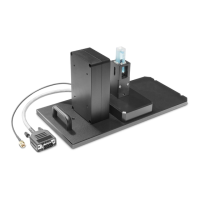
LabChip GX Instrument Description 276
V4.2 LabChip GX User Manual PerkinElmer
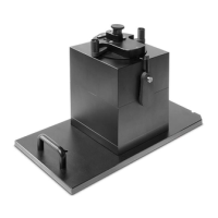
Chip Cartridge (Continued)
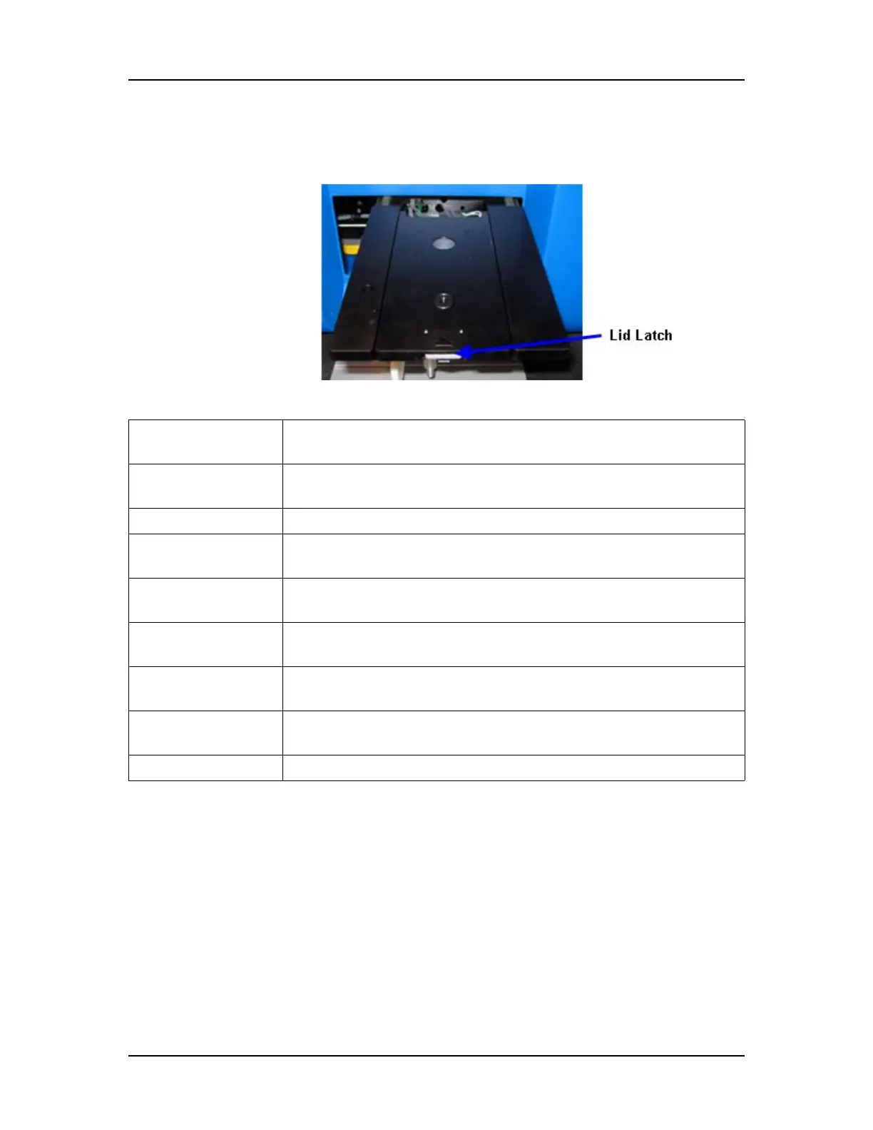
Figure 136. Lid Latch
High Voltage Interface
Supplies DC voltage to the separation channels in the chip via inert
electrodes that are immersed in specific wells on the chip. There
are 6 voltage channels for the LabChip GX chips. HV channels can
be run in either constant voltage or constant current mode.
Lid Holds the electrodes and o-rings to supply voltage and
pressure to the chip.
Bottom of Cartridge Holds the chip. The sipper on the chip extends through the
sipper slot.
Optical Window Window for laser to illuminate chip.
Optical Beam
Dump
Provides an optically dark background under the chip.
Pressure Plate with
Heating Element
Maintains a constant temperature in the chip’s microfluidic
channels.
Electrodes Apply voltage to the chip to move fluid through the chip and
drive electrophoretic separations in the chip channels.
O-Rings Create a seal between the chip cartridge and the chip to apply
pressure or vacuum to the wells.
Pressure Port Supplies pressure (positive or negative) to prime the chip or
move samples through the chip.
Lid Latch Locks the chip cartridge closed.
 Loading...