Program instructions
7.13 Program control
S7-200 SMART
System Manual, 09/2015, A5E03822230-AC
307
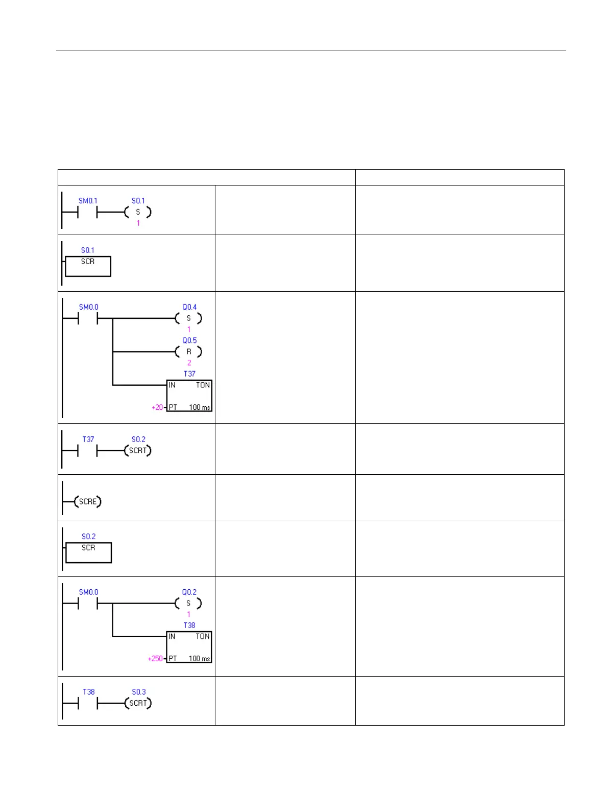
Example: SCR sequential control flow
In the following sample program, the first scan bit SM0.1, is used to set S0.1, which will be
the active State 1 on the first scan. After a 2-second delay, T37 causes a transition to State
2. This transition deactivates the State 1 SCR (S0.1) segment and activates the State 2 SCR
(S0.2) segment.
On the first scan enable state 1.
LD SM0.1
S S0.1, 1
Beginning of state 1 control
region.
LSCR S0.1
Control the signals for street 1:
1. Set: Turn on the red light.
2. Reset: Turn off the yellow
and green lights.
3. Start a 2-second timer.
LD SM0.0
S Q0.4, 1
R Q0.5, 2
TON T37, +20
After a 2 second delay, transi-
tion to state 2.
LD T37
SCRT S0.2
End of SCR region for state 1.
SCRE
Beginning of state 2 control
region.
LSCR S0.2
Control the signals for street 2:
1. Set: Turn on the green light.
2. Start a 25-second timer.
LD SM0.0
S Q0.2, 1
TON T38, +250
After a 25 second delay, transi-
tion to state 3.
LD T38
SCRT S0.3

 Loading...


