Maintenance
1132−2/A1
RT-flex50-D
Wärtsilä Switzerland Ltd
3/ 17
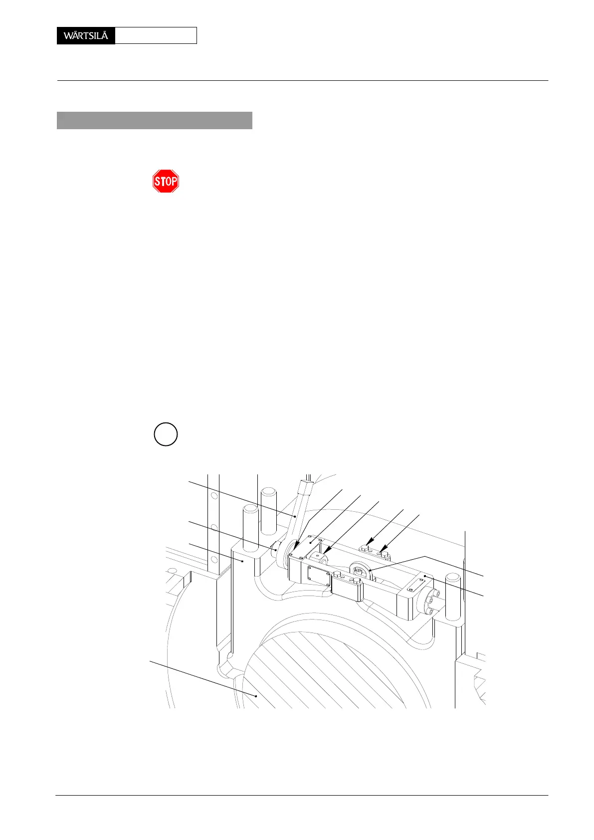
2. Placing of thrust device 94110
Thrust device 94110 must be used for expanding the upper part of main bearing
cover 3, facilitating the removal from its guide in bearing girder 2.
Attention! Never use tool 94110 as a lifting device, i.e. attaching a rope to the
thrust device!
Moreover, it must be handled carefully and not be changed, as its length corre-
sponds to a specified dimension.
D Turn crank to exhaust side approx. 90_ after T.D.C.
D Place working platform.
D Check the bearing clearance (see 0330−1).
D Loosen the waisted studs and remove their nuts.
⇒ Fit lifting lug 94116b onto the bearing cover using screws 8.8/M12x28.
⇒ Fasten thrust device 94110 as instructed on name plate 13:
− Apply MOLYKOTE G-RAPID PLUS to the spindle of special screw 9 and
thrust piece 11 each time before use.
− Completely turn back the spindle.
− Place impact ring spanner 8, fit the thrust device to the bearing cover us-
ing screws 12 and tighten them with 24 Nm.
− Expand the bearing cover by turning special screw until it rests on nut 10.
B
018.595/09
11
8
3
94116b
12
DP
10
13
94110
9
1
50−D / 2010
Removal and Fitting of a Main Bearing