Maintenance
9223−1/A1
RT-flex50-D
Wärtsilä Switzerland Ltd
3/ 22
1.3 Inner shaft encoder
Removing the inner shaft encoder 13a is only possible after the toothed belt of the
outer shaft encoder 13 has been removed according to paragraph 1.2.
Removal of the inner shaft encoder 13a is carried out analogously to the outer one.
008.727/00
008.726/00
C
SK
I
I
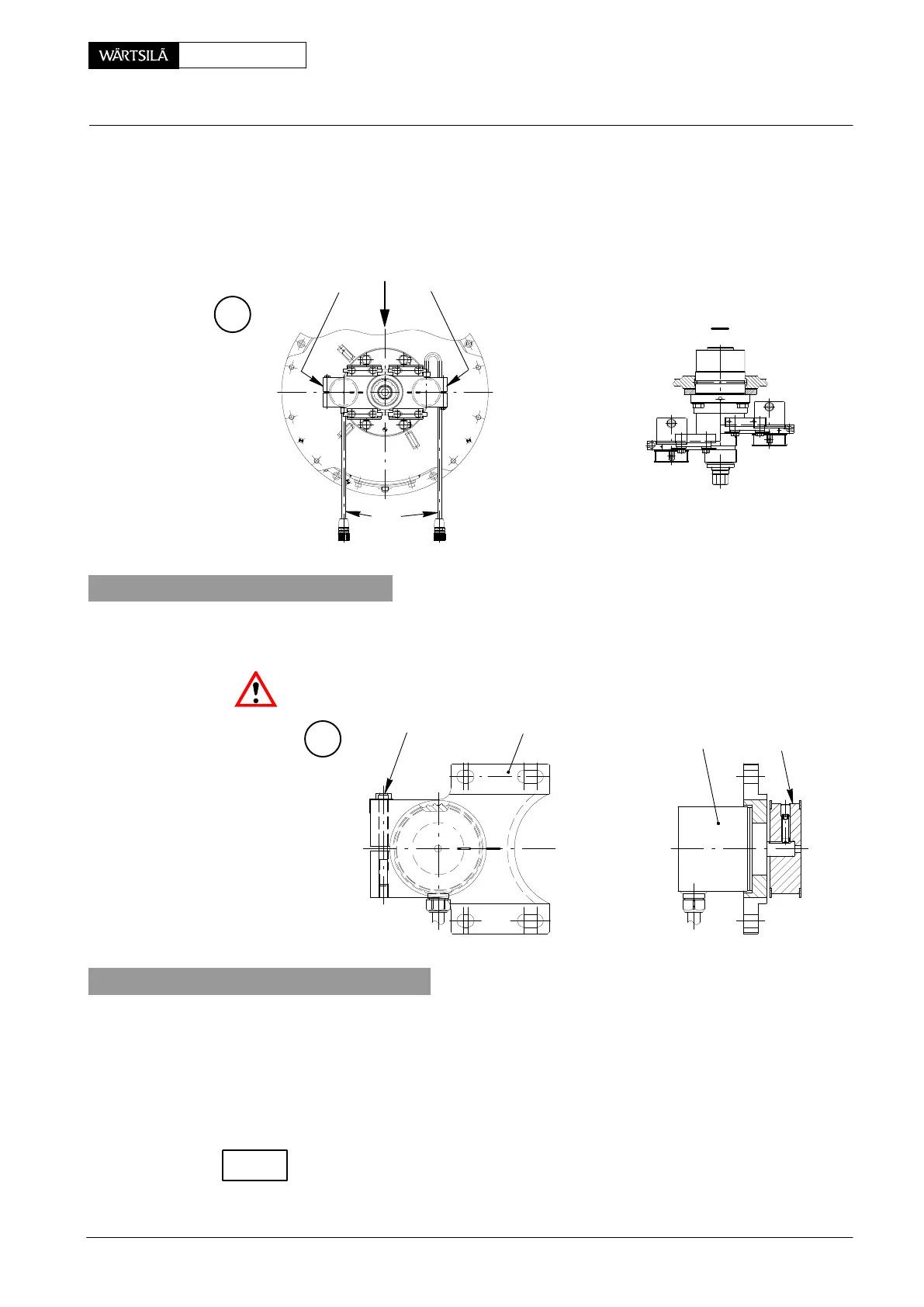
2. Shaft encoder
Shaft encoders are only supplied complete. The crank angle sensor 6 is fastened
to the holder 7 and set by the manufacturer.
Attention! Never loosen screw 8!
008.728/00008.728/00
7
D
6 19
8
3. Fitting the shaft encoder
3.1 Inner shaft encoder
⇒ Turn crankshaft to T.D.C. of Cyl. No.1.
⇒ Mount shaft encoder 13a (Fig. ’D’ and ’F’) on the guide plate of bearing hous-
ing 14 with screws 15, washers 16 and locking plates 17. Do not tighten
screws 15. Apply MOLYKOTE paste G to the threads and head seatings.
Slide shaft encoder along the guide plate to check that the shaft encoder is moving
freely.
⇒ Push shaft encoder inwards.
2012-07
rank Angle Sensor Unit: Dismantling, Assembling and Adjusting
CHECK