Maintenance
8733−1/A1
RT-flex50-D
Wärtsilä Switzerland Ltd
1/ 4
Tools: Key to Illustrations:
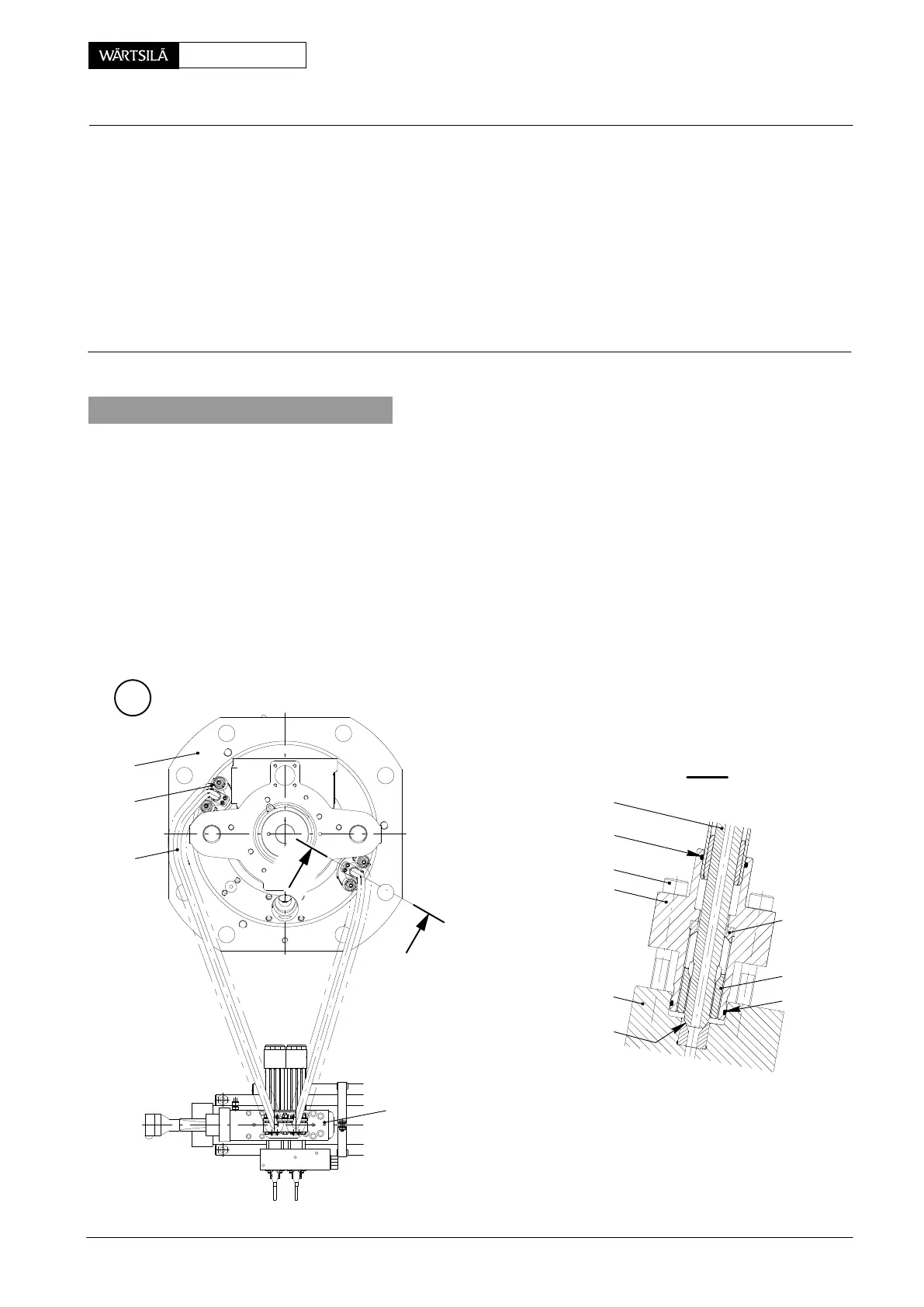
1 Regrinding device 94870 1 Cylinder cover 9 Flange
consisting of: 2 Injection valve 10 Drain screw
1 Screw-on sleeve 94870a 3 Fuel pressure pipe 11 O-ring
1 Grinding tool 94870b 4 Injection control unit 12 O-ring
1 Lock nut 94870c 5 Claw
1 Template 94870d 6 Head screw DF Sealing face
7 Flange EC Emery cloth
1 Torque wrench 8 Thrust ring HD Hand drill
1. Removal
When working on a fuel pressure pipe 3 the engine has to be stopped, and it is
essential that instructions 0510−1 in the Operating Manual be strictly followed.
⇒ Carefully loosen drain screws 11 by several turns in order to drain fuel oil.
⇒ Remove head screws 6 from flange 7 on injection valve 2 (Fig. ’A’) and injec-
tion control unit 4 (Fig. ’C’) and then remove fuel pressure pipe 3.
D Pay attention not to damage sealing faces ’DF’ when removing fuel pressure
pipes 3.
D All connections must be closed off immediately and sealing faces ’DF’ must be
protected after removing fuel pressure pipes.
A
2
1
3
I - I
3
11
6
7
2
8
5
12
DF
013.316/05
I
013.314/05
I
4
uel Pressure Piping
emoving, Fitting and Regrinding of Sealing Faces
2010