Maintenance1132−2/A1 RT-flex50-D
Wärtsilä Switzerland Ltd
12/ 17
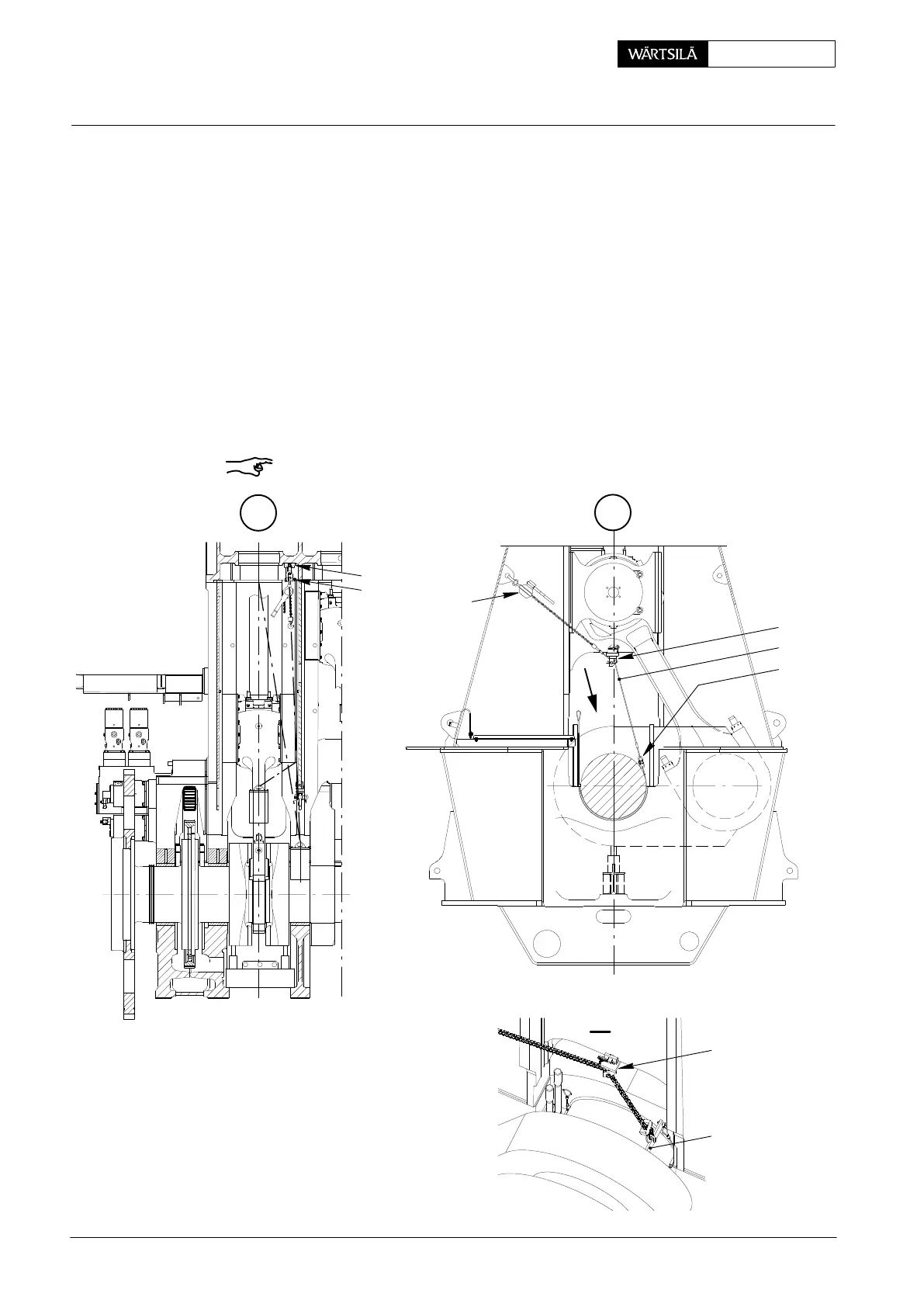
5.4 Turning out lower bearing shell No. 2 and following
D Turn crank to exhaust side approx. 90_ after T.D.C.
D Place working platform.
D Crankshaft lifted up by approx. 0.2 mm (see paragraphs 5.1 and 5.2).
⇒ Remove Allen screw 5 from bearing girder on exhaust side. Fasten turning-
out device 94118a to bearing shell 4a (see detail in Fig. ’J’), lead both ropes
along the lateral edges of the bearing shell to the other side and connect them
with device 94119b.
⇒ Fit assembling and dismantling device 94117 to column by means of its prop-
er pin, which must be secured with a double spring clip.
⇒ Pull rope 94120a through the assembling and dismantling device and hook
the ends in manual ratchet H
1
and the device.
⇒ Turn out bearing shell using manual ratchet H
1
until transportation tool
94116a (WLL 50 kg) can be fitted.
Remark: If necessary, manual ratchet H
1
can be hooked straight into the device
for turning out the last part of the bearing shell.
K
018.608/09
L
94120
94119b
94117
94119
I
I
H
1
018.605/09
94332
94332a
94117
2010 / 50−D
Removal and Fitting of a Main Bearing