Maintenance
3103−1/A1
RT-flex50-D
Wärtsilä Switzerland Ltd
3/ 3
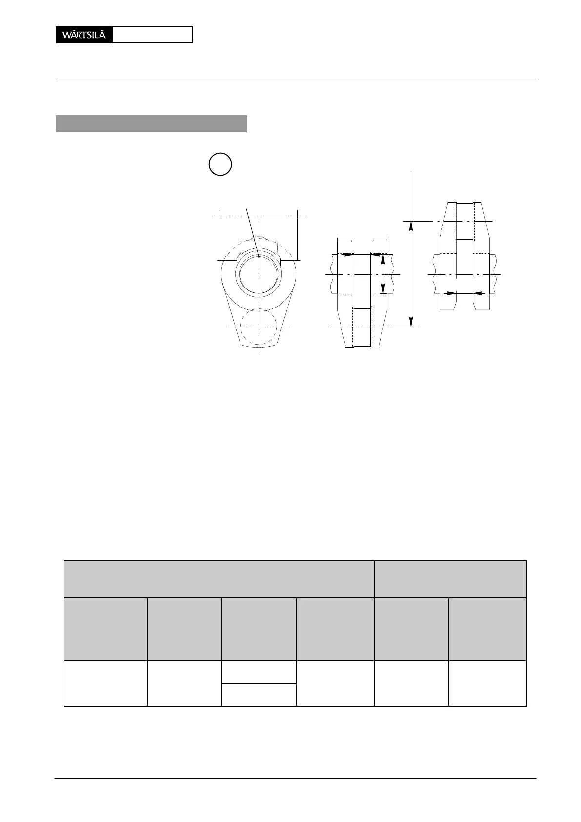
5. Judging the measuring
STROKE
D
94305
C
nB.D.C
nT.D.C
The difference between the indicated values shows the amount of crank deflection
during one revolution (Fig. ’B’).
Where values are measured which lie above the maximum permissible limits, the
cause has to be found and the necessary remedial measures taken (defective
main bearing, engine stay altered due to hull deformation, loose holding-down
bolts, defective propeller shaft bearings or checking equipment 94305, etc.).
The values given below are valid for all conditions independent of outside in-
fluences, however considering notes
1)
to
3)
:
1)
For engine without torsional vibration damper or front disc.
2)
For engine with torsional vibration damper or front disc.
3)
This value is not a limit for final acceptance, but it is used as an indicator that
further investigations are required.
Vertical values
(B.D.C. − T.D.C.)
Horizontal values
(EXHAUST SIDE − FUEL SIDE)
Cylinder No. 1
at DRIVING END
Cylinder No. 2
and following
or Cylinder at
FREE END
1)
Cylinder at
FREE END
2)
Max. deviation
between two
adjacent Cyl.
3)
all Cylinders Max. deviation
between two
adjacent Cyl.
3)
± 0.58 mm ± 0.36 mm ) 0.36 mm 0.22 mm ± 0.14 mm 0.09 mm
* 0.37 mm
2011-12
Measuring Crank Deflection