Maintenance
1112−1/A1
RT-flex50-D
Wärtsilä Switzerland Ltd
1/ 3
Tools: Key to Illustrations:
1 Feeler gauge 94122 1 Vent screw 11 Nut
1 Pre-tensioning jack 94145 2 Cylinder 12 Conical socket
1 HP oil pump 94931 3 Piston 13 Seating washer
2 Hydr. distributors 94934a 4 Nut
1 HP hose 94935 5 Bedplate
6 Foundation bolt BN Limiting groove
7 Foundation fitted stud EV Relief valve
8 Sleeve KO Slot
9 Chock RS Round bar
10 Ship’s foundation plate SA Gap
1. General
The pre-tension of the foundation bolts (holding down studs) must be checked at
longer intervals e.g. during overhauls (see 0380−1).
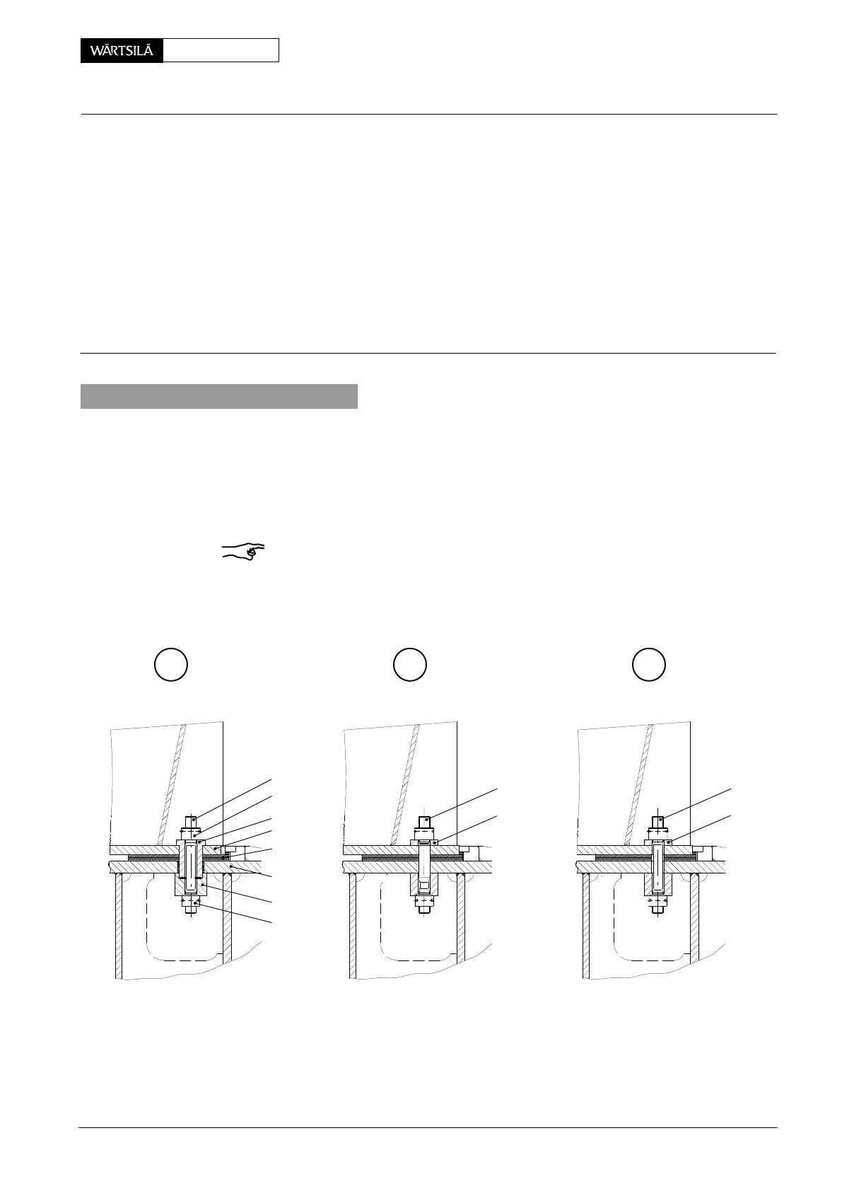
In the area of the thrust bearing the foundation may be fastened with foundation
bolts 6 and sleeves 8 (Fig. ’A’) or with foundation fitted studs 7 (Fig. ’B’).
The remaining area is fastened with foundation bolts 6, however without sleeves 8
(Fig. ’C’).
Remark: Pay attention to the General Application Instructions 9403−4 for the
hydraulic pre-tensioning jacks.
A C
012.948/05
6
13
7
B
10
12
11
8
5
4
9
13
6
edplate and Thrust Bearing
hecking the Foundation Bolts
2010