Maintenance2722−1/A1 RT-flex50-D
Wärtsilä Switzerland Ltd
8/ 8
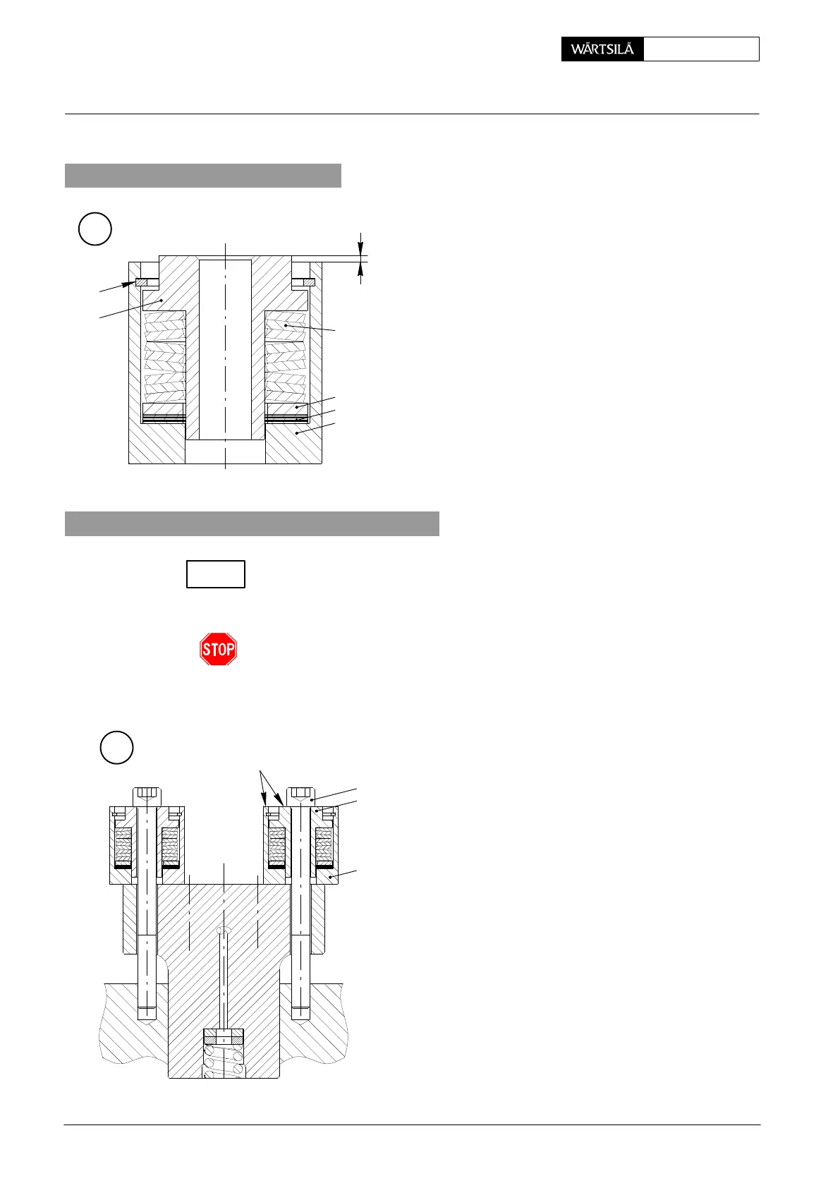
9. Assembling a spring cage
− Cup springs 4 are fitted in spring cage 23.
− The spring packet consists of three packs com
posed of three cup springs which are arranged a
shown in Fig. ‘E’.
In order to maintain an equal contact force when screw
ing down the injection valve, distance ’x’ must b
adjusted to 1.6 ± 0.1 mm with shims 26 .
4
E
25
26
011.473/04
23
24
3
x
10. Fitting an injection valve in cylinder cover
Clean the seating surface of the injection valve in the cylinder cover and check for
damages.
If necessary recondition the seating surface using the special tool supplied with the
tools set (see 2708−3).
The sealing must be metal-to-metal, i.e. no joint must be put in between.
⇒ Place the injection valve carefully in the cylinder cover. Dowel pin 22 (Fig. ’B’)
assures the correct position.
10.1 Screwing down the injection valve
⇒ Apply Never-Seez NSBT-8 to the threads and th
seating surfaces of Allen screws 2.
⇒ Fit and equally tighten Allen screws 2 until sprin
guides 3 are flush with spring cages 23.
F
FLUSH
2
3
23
013.504/05
2010
Injection Valve: Checking, Dismantling, Assembling and Adjusting
CHECK