Maintenance
1203−1/A1
RT-flex50-D
Wärtsilä Switzerland Ltd
1/ 2
Tools: Key to Illustrations:
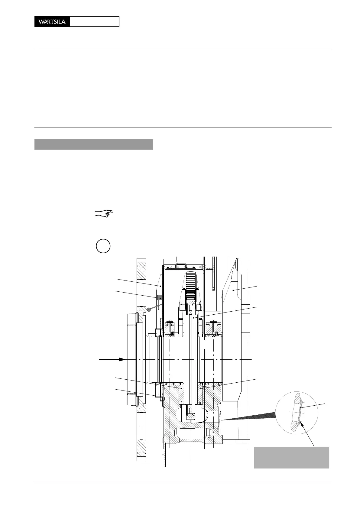
1 Inside micrometer 94101 1 Coupling flange 6a Thrust bearing pads
1 Feeler gauge 94238 2 Oil baffle, upper part for AHEAD
3 Oil baffle, lower part 7 Cover
4 Thrust flange 8 Dial gauge
5 Crankshaft with magnetic base
6 Thrust bearing pads
for ASTERN
1. Measuring method 1
The total displacement which results from pushing the crankshaft axially both
ways until it contacts the thrust bearing pads AHEAD and ASTERN, is measured
with dial gauge 8. This is then checked against the figure marked on the page
’Check Dimensions’ in the engine documents supplied (see also Clearance Table
0330−1’Crankshaft and main bearing’).
An increase compared with the nominal figure signifies wear of the thrust bearing
pads.
Remark: After major works have been carried out in the thrust bearing space dis-
mantle cover 7 for a check-up on the thrust bearing housing. Remove any foreign
matters through the opening.
A
6a
2
THRUST
012.968/05
8
6
3
4
5
CHECK HOLE FOR
FREE PASSAGE EVERY
6000−8000 OP. HOURS
hrust Bearing
hecking the Axial Clearance
2010