Maintenance
9223−1/A1
RT-flex50-D
Wärtsilä Switzerland Ltd
17/ 22
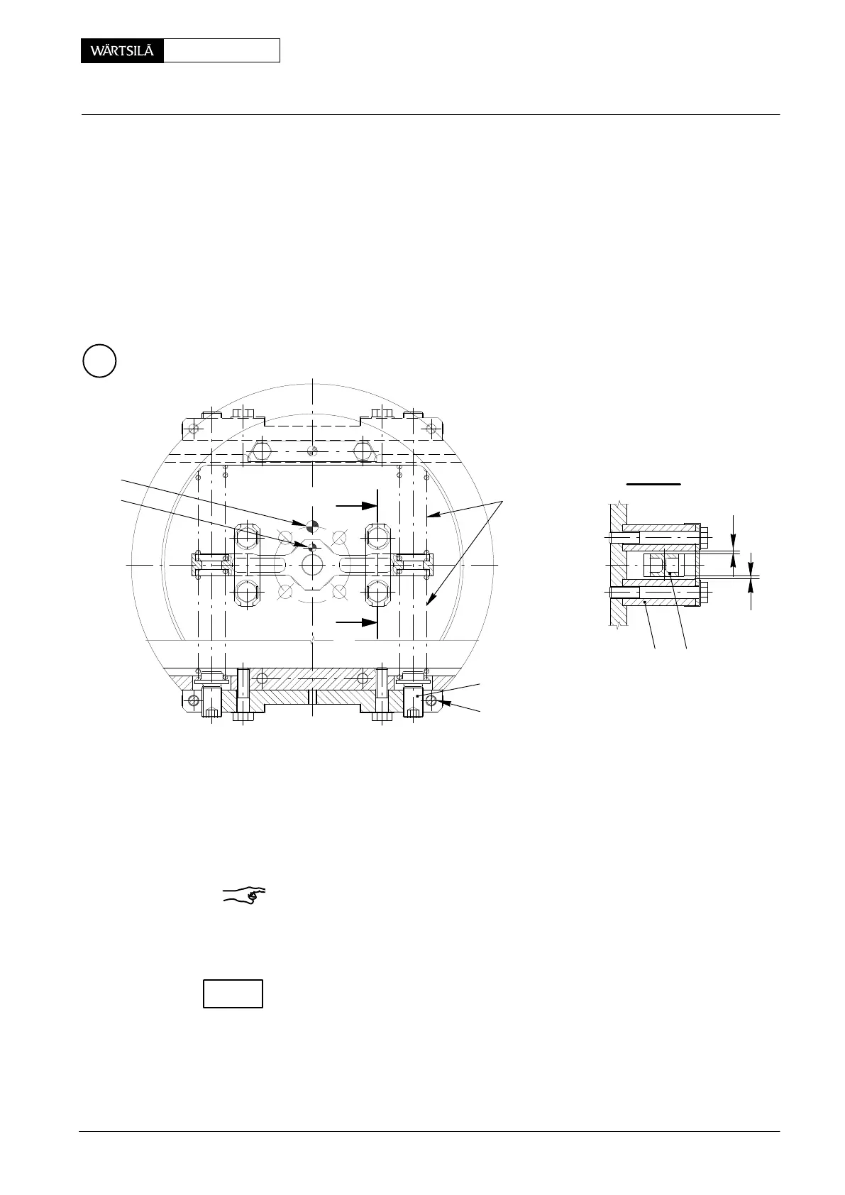
8.5 Adjusting the compression spring
⇒ By means of synchronously adjusting screws 54 (i.e. if one of the adjusting
screws is screwed-in by e.g. ½ turn, the opposite one must be screwed-out by
½ turn) move the relevant compression spring pair 42 until lever 43 shows the
same distance ’x’ between the stops on both sides (centering lever).
For measuring use feeler gauge 94122.
⇒ Tighten all clamp screws 55 with a torque of 35 Nm and lock them.
008.752/01
008.749/01
Z
II
II
II - II
42
55
4356
x
x
54
40
50
8.6 Fitting the connecting unit (Fig. ’W’)
⇒ Fit waisted screw 20 and screw 44 with new locking plates. Tighten and lock
the latter (Fig. ’U’ view I).
Remark: Screw 44 must not press against waisted screw 20!
⇒ Fit connecting unit 49 and screws 48 together with new locking plates 48a,
applying MOLYKOTE paste G to threads and seating surfaces.
⇒ Tighten screws 48 with a torque of 60 Nm and lock them.
Locating pin 40 and locating pin 50 must point upwards on Cyl. No.1 at T.D.C. ac-
cording to Fig. ’W’ and ’Z’!
2011
rank Angle Sensor Unit: Dismantling, Assembling and Adjusting
CHECK