Maintenance
2722−1/A1
RT-flex50-D
Wärtsilä Switzerland Ltd
7/ 8
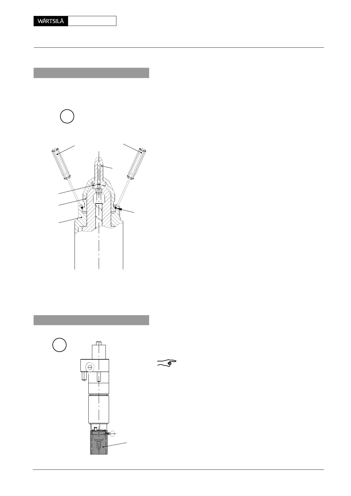
7. Replacing a nozzle tip
If nozzle tip 7 should be dismantled only, it is sufficient t
remove retaining sleeve 14.
7.1 Removal
⇒ Using two screw drivers inserted between both re
cesses in retaining nut 10, press snap ring 15 ou
of the groove in the retaining nut, whereby the re
taining sleeve can be withdrawn (Fig. ’C’).
Watch that the snap ring does not jump off unex
pectedly.
⇒ Remove nozzle tip.
7.2 Fitting
For fitting it is advantageous to clamp the injectio
valve on its flange into a vice (nozzle body 13 pointin
upwards), and then proceed as follows:
⇒ Clean all parts with clean diesel oil or kerosine an
blow them out with compressed air.
⇒ Place nozzle tip on the nozzle body whereby th
position is assured by dowel pin 16.
⇒ Put retaining sleeve 14 over the nozzle tip, an
press snap ring 15 into the groove of the retainin
nut by means of the screw drivers.
After replacing a nozzle tip the injection valve must b
checked and judged according to sections 2 and 3.
C
SCREW DRIVER
15
16
14
10
7
013.493/05
8. Protecting a nozzle tip
D
013.494/05
Remark: To protect the nozzle tip integrated in the in
jection valve against damage, always fit protection ca
94271 for transport, storage, etc.
94271
2010
Injection Valve: Checking, Dismantling, Assembling and Adjusting