Maintenance2303−1/A1 RT-flex50-D
Wärtsilä Switzerland Ltd
2/ 6
2. Removing, dismantling and assembling
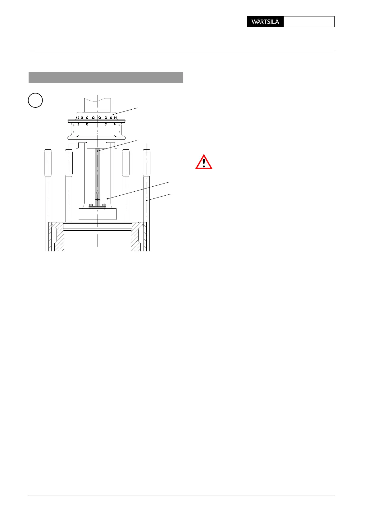
1
18
94345
A
013.223/05
12
2.1 Removing a gland
⇒ For removing the gland, both distanc
holders 94345 are to be screwed o
the foot of piston rod 18.
⇒ Unscrew the four inner screws 10
support 16 (Fig. ’B’ section II-II).
Attention! For reasons of safety, th
eight outer screws 15 to support 16 are
be loosened and removed after disma
tling the gland (Fig. ’B’).
⇒ Remove the gland including the pisto
(see 3403−1 ’Removal of a piston’).
2.2 Dismantling a gland
⇒ Place the piston in piston supporting device 94350. For this 2-part housing 1
of the gland must rest on the two hinged covers 19 of the device.
⇒ Loosen and remove fitted bolts 13b and screws 13 to 2-part housing 1.
⇒ Push the two gland housing halves away from the piston rod.
⇒ Remove all tension springs, scraper rings, sealing rings and ring supports.
⇒ On the following parts wear has to be measured (see Fig. ’D’):
− Scraper rings 2 and 6
− Sealing rings 3 and 4
D The admissible wear on the wearing parts is indicated in Clearance Table
0330−1 ’Piston rod gland’. Parts which are beyond the admissible tolerance
must be replaced.
D If necessary remove scraper rings 6 from ring supports 5 and replace them
with new ones.
D Defective tension springs 8, 9 and O-ring 20 have to be replaced with new
ones.
2010
Piston Rod Gland: Dismantling and Assembling, Measuring the Wear