Maintenance2303−1/A1 RT-flex50-D
Wärtsilä Switzerland Ltd
4/ 6
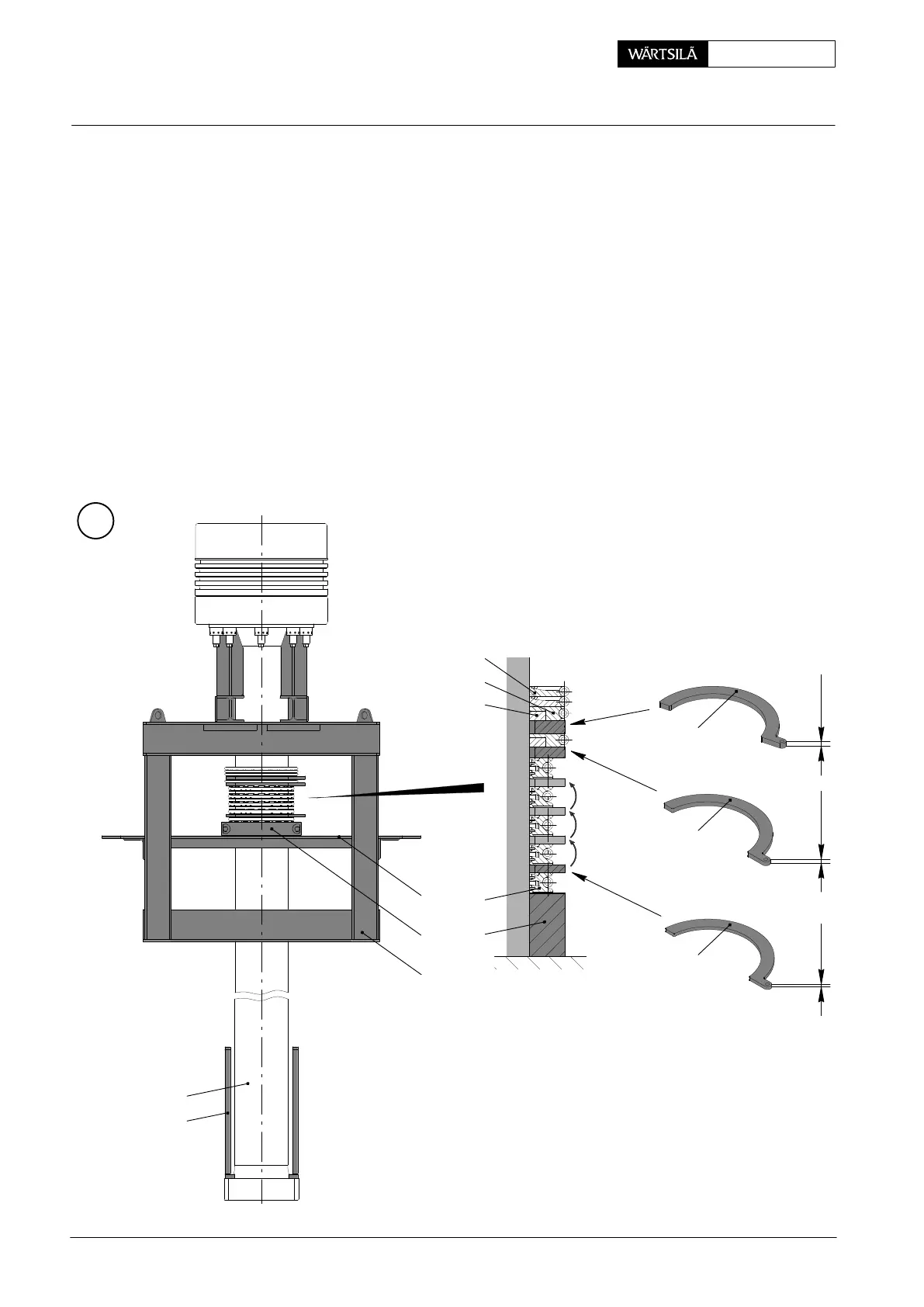
2.3 Assembling a gland
⇒ Place the piston in piston supporting device 94350, its hinged covers 19 must
be folded down.
⇒ Attach clamp ring (2-part) 94345b − resting on the hinged cover − to piston rod
18.
⇒ Place the three parts of a ring support 5 on the clamp ring with scraper ring 6
fitted. Distribute the distances evenly.
⇒ Use assembly tool 94345e (see 9403−5) for fitting tension spring 9.
⇒ Place two distance pieces 94345f (9 mm) on ring support 5 and fit another ring
support with scraper ring 6 and tension spring 9 as described above.
D The height of distance pieces 94345f corresponds to the respective web
height of the ring grooves in 2-part housing 1.
C
4
13 mm11 mm9 mm
009.656/02
009.655/02
009.654/02
3
2
5
94345b
94350
94345f
94345f
94345f
016.571/08
19
94345
18
2010
Piston Rod Gland: Dismantling and Assembling, Measuring the Wear