Maintenance
2303−1/A1
RT-flex50-D
Wärtsilä Switzerland Ltd
5/ 6
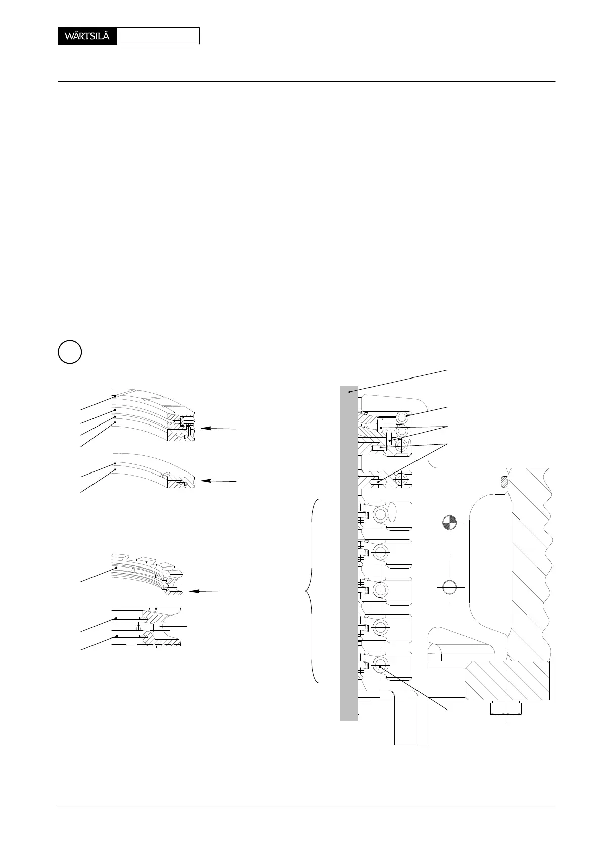
⇒ After assembly of the ring supports for grooves ’c’ − ’g’, place two distance
pieces 94345f (11 mm) on the uppermost ring support 5 and fit sealing rings 3,
4 and tension spring 8 for groove ’b’.
D Take care that one segment is always provided with two horizontal locating
pins 7a lying side by side on sealing ring 4. These locating pins must fit into the
corresponding bores in sealing ring 3. Remove possibly existing vertical locat-
ing pins 7.
The remaining three segments are provided only with one horizontal locating
pin each.
⇒ Place two distance pieces 94345f (13 mm) on the assembled sealing ring 3
and fit again sealing rings 3, 4 and two scraper rings 2 with tension springs 8
for groove ’a’.
D Proceed in the same way as mentioned above for sealing rings 3 and 4, how-
ever, a vertical locating pin 7 in sealing ring 3 must fit into the respective recess
in scraper ring 2.
No vertical locating pin may be fitted in the uppermost scraper ring.
D
3
5
6
4
2
2
3
4
6
GROOVE b
GROOVE a
GROOVES c−g
7
8
7a
18
9
013.225/05
2010
Piston Rod Gland: Dismantling and Assembling, Measuring the Wear