Maintenance
3301−2/A1
RT-flex50-D
Wärtsilä Switzerland Ltd
1/ 2
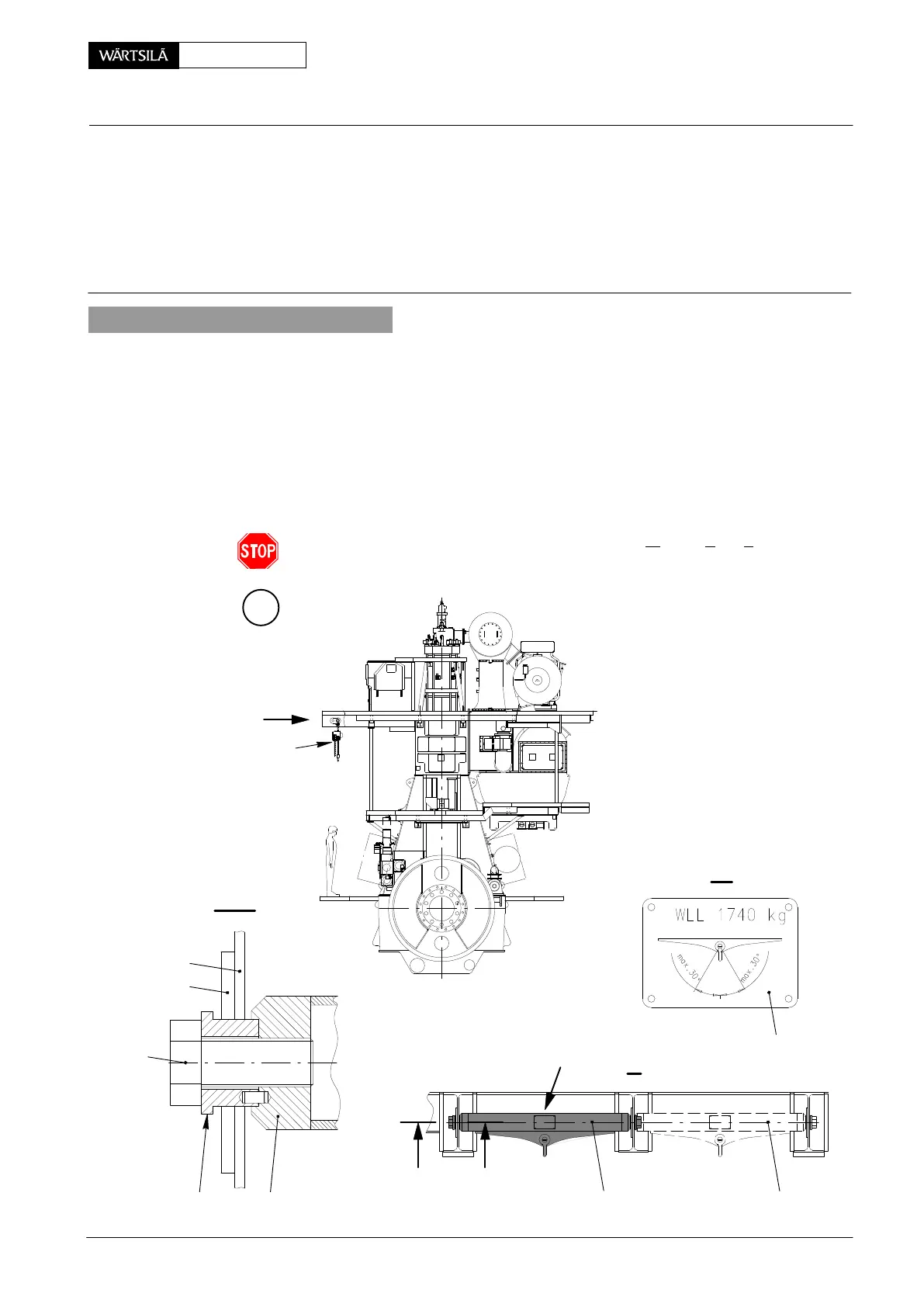
Tools: Key to Illustrations:
1 Spur-geared chain block a 1 Double I-girder (upper platform)
2 Spur-geared chain blocks b 2 Reinforcing rib
1 Lifting tool 94335(a) 3 Name plate
2 Bushes 94335b 4 Crane rail
2 Screws 94335c 5 Stop piece
1. General
For removal and fitting of heavy engine components there are two variants for their
suspension on fuel side, i.e. with lifting tool 94335(a) (variant A) or with a continu-
ous crane rail (variant B).
The working procedures however, are for both variants identically as described in
3303−2 to 3303−5 and 3326−2.
Lifting tool 94335(a) is placed between reinforced double I-girders 1, paying atten-
tion attention to the position of spring dowel pin, and tightened by means of screws
94335c.
With the admissible lifting capacity WLL=1740 kg (W
orking Load Limit) the strand
angle of 30_ may not be exceeded!
I
I
A
I - I
a
II
I
II
I
2
94335c
3
1
018.385/09
pper Platform
rrangement of Lifting Tools
2010