Maintenance
9223−1/A1
RT-flex50-D
Wärtsilä Switzerland Ltd
11/ 22
6. Assembling the crank angle sensor drive
⇒ Clean all parts and check their conditions prior to assembling.
⇒ Replace sealing ring 30, ball bearings 32, 32a and O-ring 60 (Fig. ’N’).
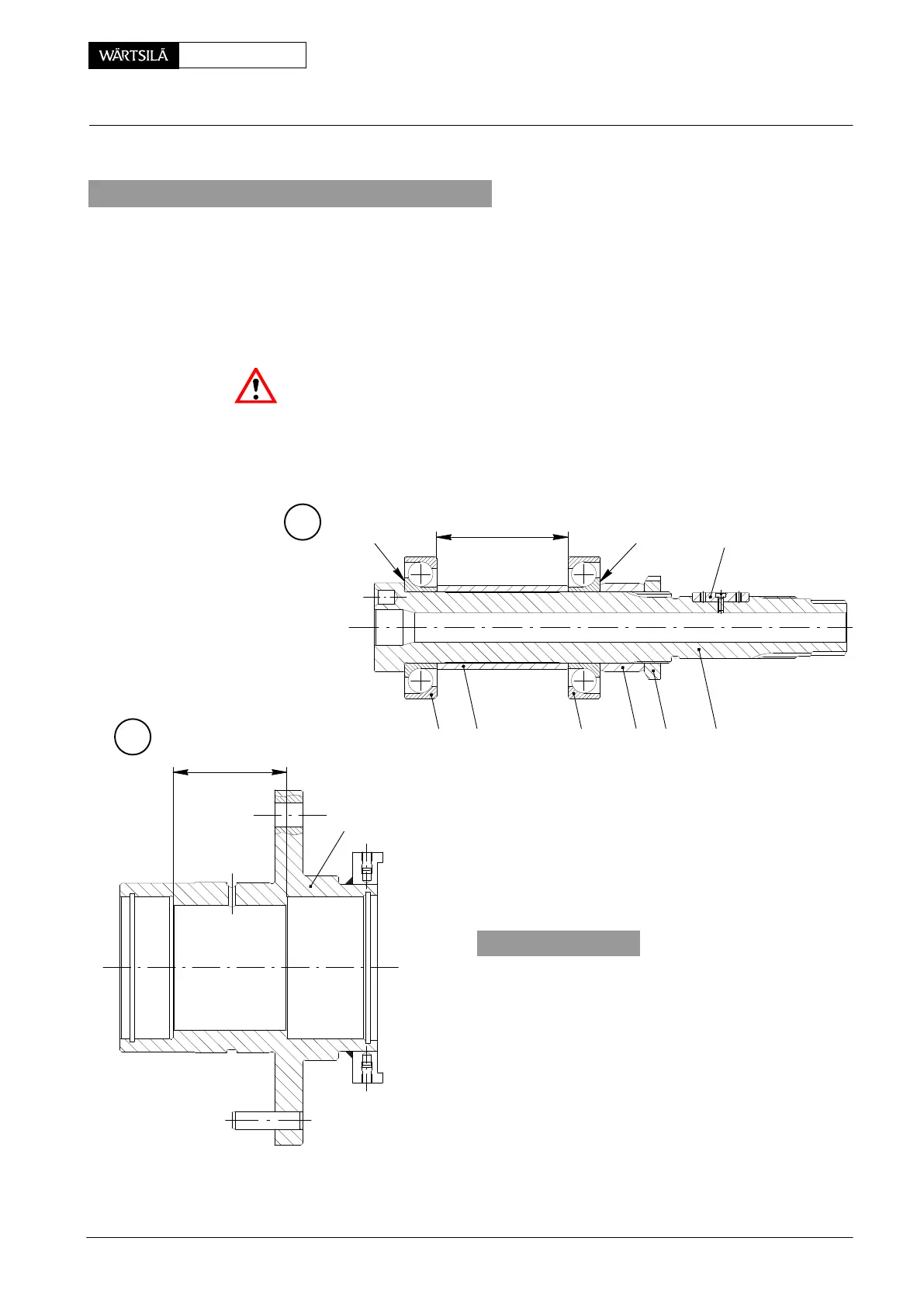
6.1 Determining of thickness ’x’ of distance ring 33 (Fig. ’N’)
⇒ Push ball bearing 32a, distance sleeve 34, ball bearing 32 and distance ring
31 onto the shaft 5 according to Fig. ’O’.
Attention! Big collar ’SU’ on inner ring of the ball bearings must point outwards!
⇒ Screw shaft nut 27 onto shaft 5 and lightly tighten it by means of hook spanner
94925.
⇒ Measure and note down distance ’a’.
008.741/01
008.740/0
⇒ Measure and note down distance ’b’ in housing 1
According to the following formula determine thicknes
’x’ for distance ring 33 to be fitted:
Tolerance ’x’ amounts to " 0.2 mm.
P
b
14
x = a − b − 4.2 mm
O
323432a 31 27 5
a
SU 38SU
2011
rank Angle Sensor Unit: Dismantling, Assembling and Adjusting