Maintenance2751−2/A1 RT-flex50-D
Wärtsilä Switzerland Ltd
4/ 9
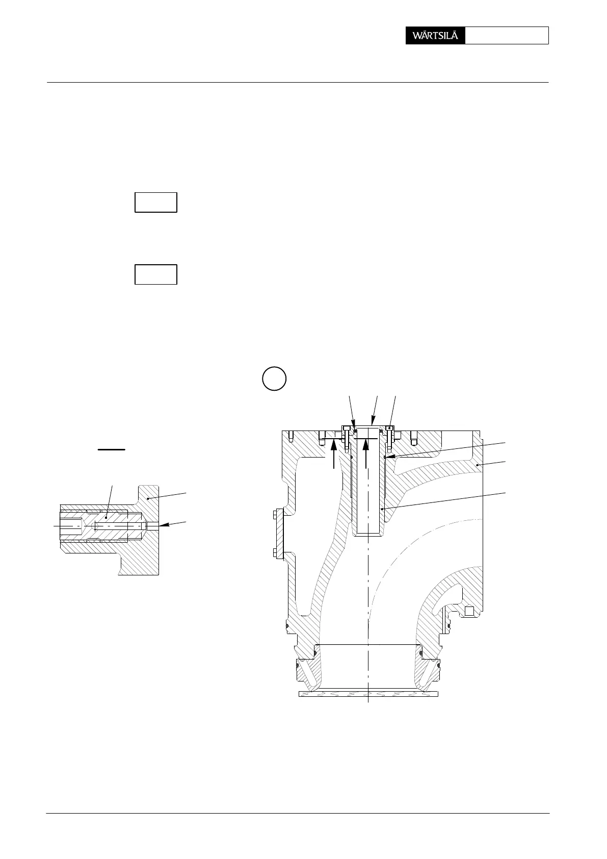
2.3 Removal of guide bush
⇒ Loosen head screws 20 and remove them together with distance ring 19 and
rod seal ring 22.
⇒ Withdraw guide bush 21 from valve cage 1 by means of two jacking screws or
threaded rods M10.
Check and measure the inner diameter of the guide bush according to Clearance
Table 0330−1 ’Exhaust Valve’.
2.4 Fitting of guide bush
⇒ Clean the bore in valve cage 1 concerned and guide bush 21.
Check oil bores ’OB’ in guide bush and throttle screws 28 for free passage.
⇒ Replace O-ring 36.
⇒ Oil and fit the guide bush.
⇒ Fit distance ring 19 and hold it provisionally tight with head screws 20.
D
I - I
20
22
19
36
1
21
OB
21
28
WCH00406
I
I
2011-12
xhaust Valve: Dismantling and Assembling
CHECK
CHECK