Maintenance
3303−2/A1
RT-flex50-D
Wärtsilä Switzerland Ltd
1/ 4
Tools: Key to Illustrations:
1 Working platform 94142 1 Connecting rod stud 9 Cylindrical pin
4 Retaining pins 94323 2 Nut 10 Upper bearing shell
3 Crank 11 Spur-geared chain block
4 Bearing cover
5 Connecting rod
6 Guide way HZ Lifting tackle
7 Lower bearing shell RC RUD-eye bolt M16
8 Allen screw RC
1
RUD-eye bolt M8
1. General
When a bottom end bearing has to be inspected or removed, nuts 2 of connecting
rod studs 1 (Fig. ’B’) have to be loosened according to the instructions in 3303−1,
for which the respective crank must be at T.D.C.
Never turn the crankshaft as long as the pre-tensioning jacks are screwed onto the
connecting rod studs.
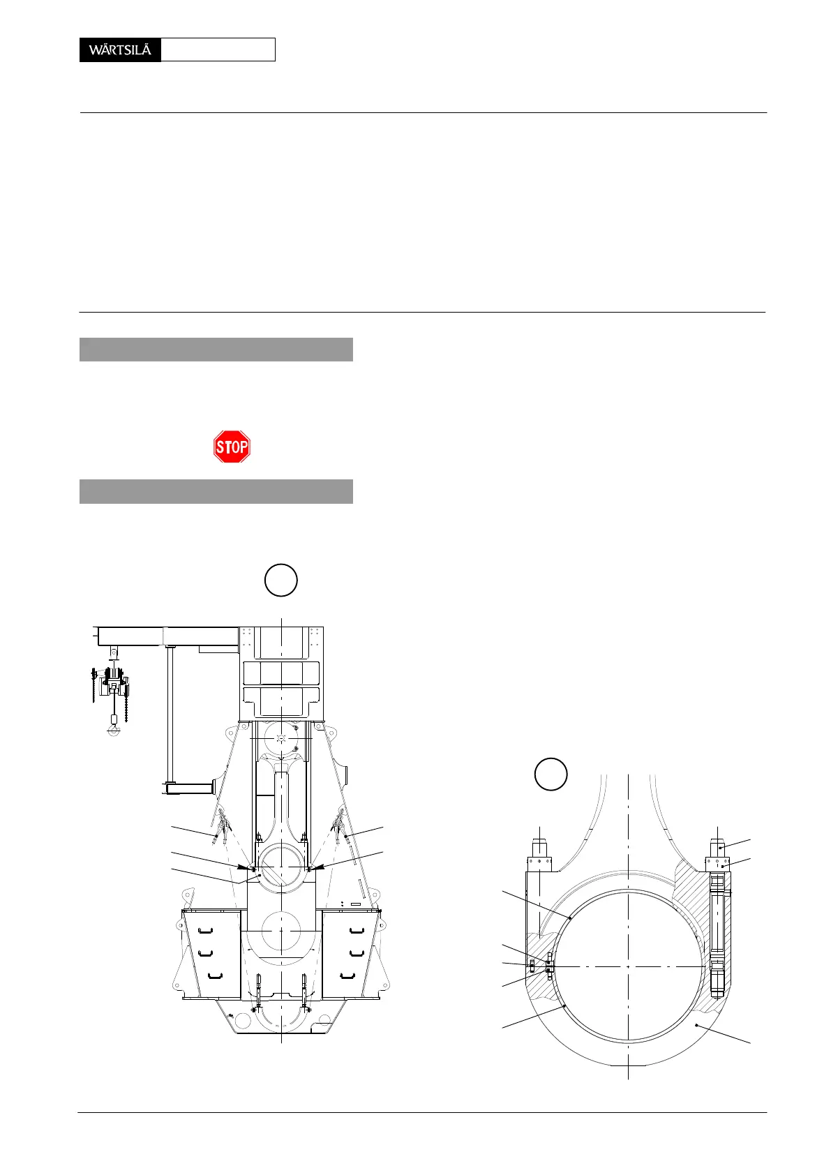
2. Inspection and removal
2.1 Lowering the bearing cover
⇒ Fit a RUD-eye bolt ’RC’ on each side of bea
ing cover 4 directly below the bearing separ
tion.
⇒ Attach lifting tackle as shown in Fig. ’A’, co
nect ropes ’a’ and ’b’ with lifting tackle ’H
and RUD-eye bolts ’RC’. Tighten the ropes
⇒ Remove nuts 2.
⇒ Carefully lower the bearing cover 4 while ta
ing care that the threads of the connectin
rod studs as well as the surface of the cran
pin are not damaged.
A
B
10
8
9
8
7
HZ
RC
HZ
RC
4
013.502/05
013.503/05
ab
onnecting Rod
nspection, Removal and Fitting of Bottom End Bearing
2010