Maintenance
3303−2/A1
RT-flex50-D
Wärtsilä Switzerland Ltd
3/ 4
F
G
013536/05
013537/05
5
HZ
3
HZ
3
8
94142
6
94323
a
X
X
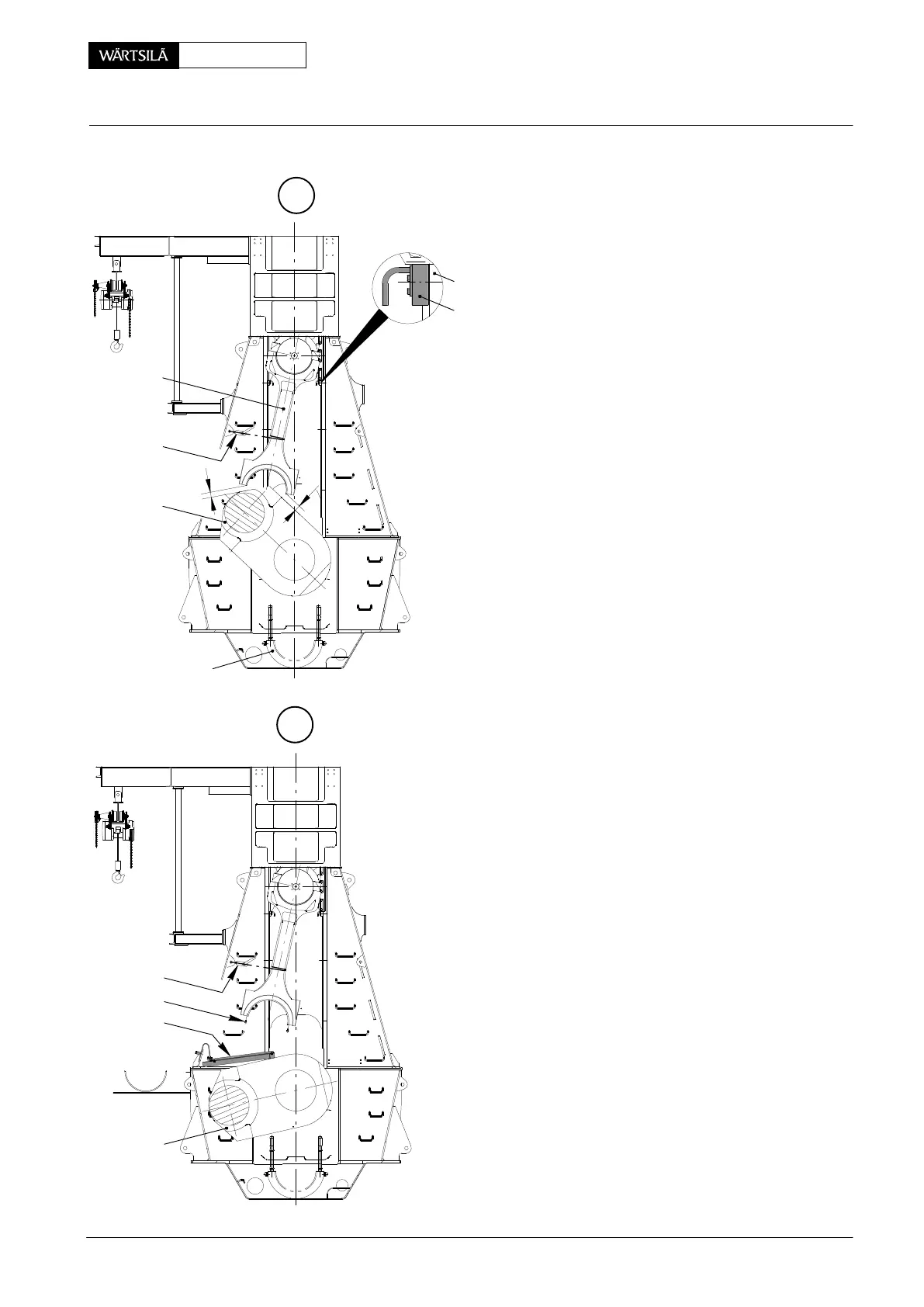
2.4 Inspection of upper bearing shell
⇒ Turn the crankshaft to T.D.C.
⇒ Insert the four retaining pins 94323 into th
bores of guide ways 6.
⇒ Carefully turn crankshaft towards fuel side
the guide shoes come to rest on the retainin
pins.
If, however, not all retaining pins touch th
guide shoes, turn them such that their ecce
trics contact the guide shoes.
⇒ Secure connecting rod 5 with rope ’a’ and li
ing tackle ’HZ’ on fuel side.
⇒ Carefully turn down the crankshaft to fu
side, following with the connecting rod bo
tom by pulling it with the lifting tackle and rop
’a’ just as far as to keep always a distance ’
between the connecting rod bearing and th
crank 3.
2.5 Removal of upper bearing shell
⇒ Turn crank 3 downwards.
⇒ Install working platform 94142 according t
the instructions in 3301−1.
⇒ Hold bearing shell and remove Allen screw
8 from the bearing shell.
⇒ Remove the bearing shell.
4
Inspection, Removal and Fitting of Bottom End Bearing
2010