Maintenance
1715−1/A1
RT-flex50-D
Wärtsilä Switzerland Ltd
1/ 2
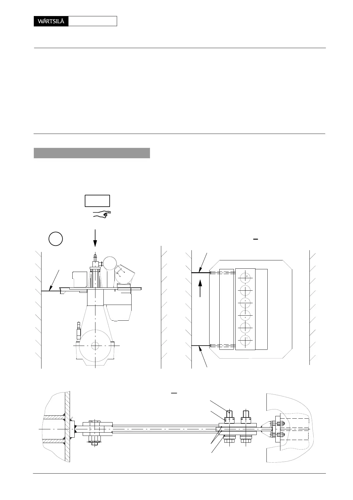
Tools: Key to Illustrations:
1 Feeler gauge 94122 1 Engine stays
1 Pre-tensioning jack 94145 2 Friction shims
1 HP oil pump 94931 3 Screw
2 Hydr. distributors 94934a 4 Nut
1 HP hose 94935 5 Disc spring BN Limiting groove
6 Vent screw EV Relief valve
7 Piston KO Slot
8 Cylinder RS Round bar
1. General
Two friction type stays 1 each are installed either on exhaust side or on fuel side as
shown in Fig. ’A’.
The pre-tension of screws 3 must be checked at specified intervals (see 0380−1).
Remark: Pay attention to General Application Instructions 9403−4 for hydraulic
pre-tensioning jacks.
II
1
1
1
FREE END
I
I
II
2
5
4
A
3
012.996/05
ngine Stays with Friction Shims
hecking the Pre-tension
2010
CHECK