Maintenance
1132−2/A1
RT-flex50-D
Wärtsilä Switzerland Ltd
9/ 17
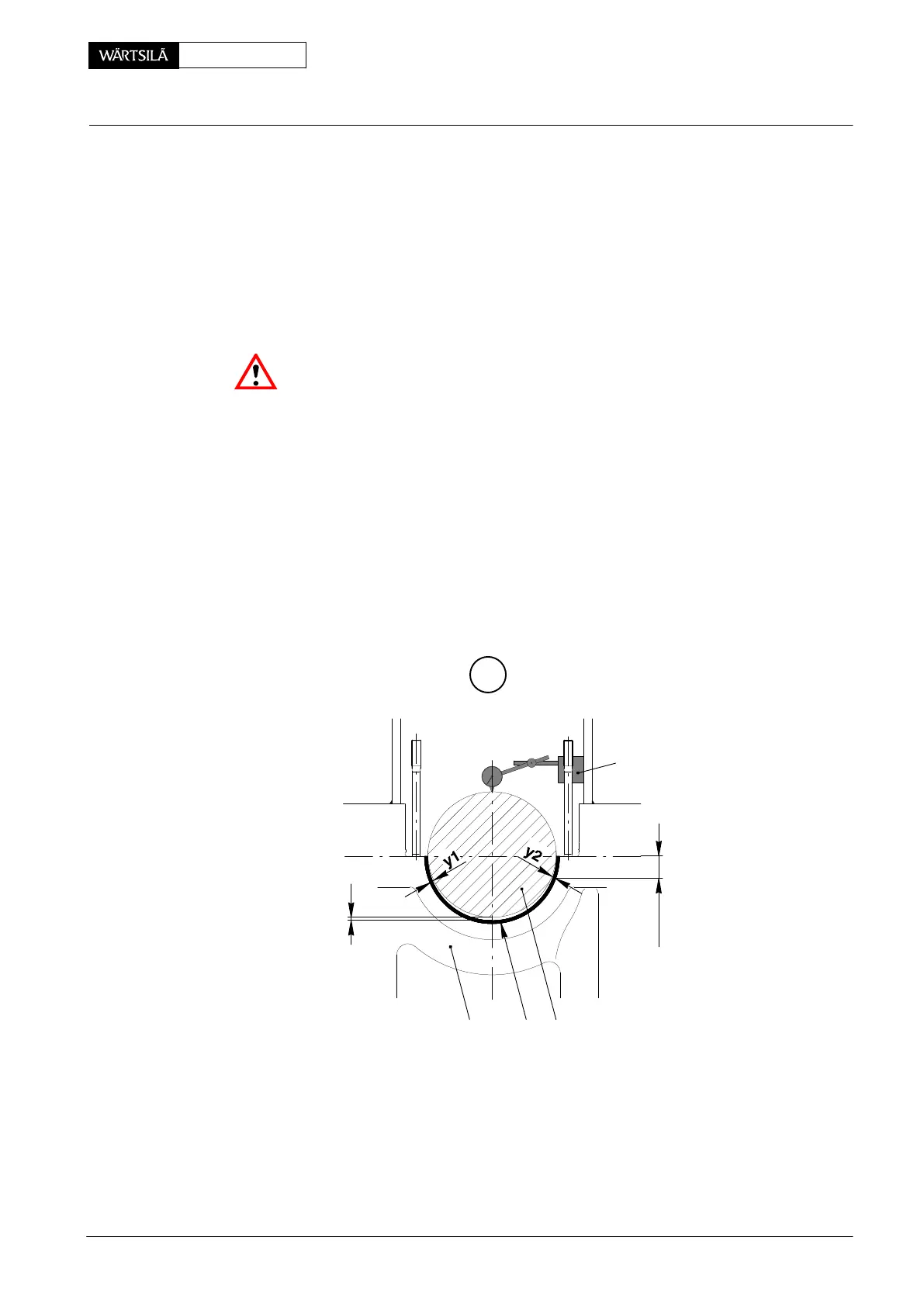
5.2 Lifting the crankshaft
⇒ Measure and note lateral bearing clearances ’y
1
’ and ’y
2
’ between crankshaft
journal 1 and lower bearing shell 4a at about 50 mm below the bearing divi-
sion.
⇒ Install dial gauge with magnetic base 17 above the crankshaft near the bear-
ing to be removed and set it to zero.
⇒ Actuate HP oil pump 94931 and lift the crankshaft by means of hydraulic jacks
94936 reaching value ’x’ = 0.2 mm (check on dial gauge).
Attention! Lift the crankshaft max. to the point where the neighbouring main bear-
ings show no vertical clearance between upper bearing shells and crankshaft.
In case the bearing shell cannot be turned out, both of the adjoining bearing
covers have also to be loosened. Thus the crankshaft can be correspond-
ingly lifted somewhat farther and the bearing shell taken out.
⇒ Keep pressure in the hydraulic jacks constant.
⇒ Measure again lateral bearing clearances ’y
1
’ and ’y
2
’, and compare the val-
ues with those from the 1
st
measurement as described above.
D If the lateral clearance has changed by more than 0.10 mm due to lifting of the
crankshaft, the latter must be lowered again and the hydraulic jacks be newly
placed in direction of the smaller clearance. Subsequently lift the crankshaft
again.
H
x
50 mm
009.810/02
17
14a2
50−D / 2010
Removal and Fitting of a Main Bearing