Maintenance
2751−2/A1
RT-flex50-D
Wärtsilä Switzerland Ltd
1/ 9
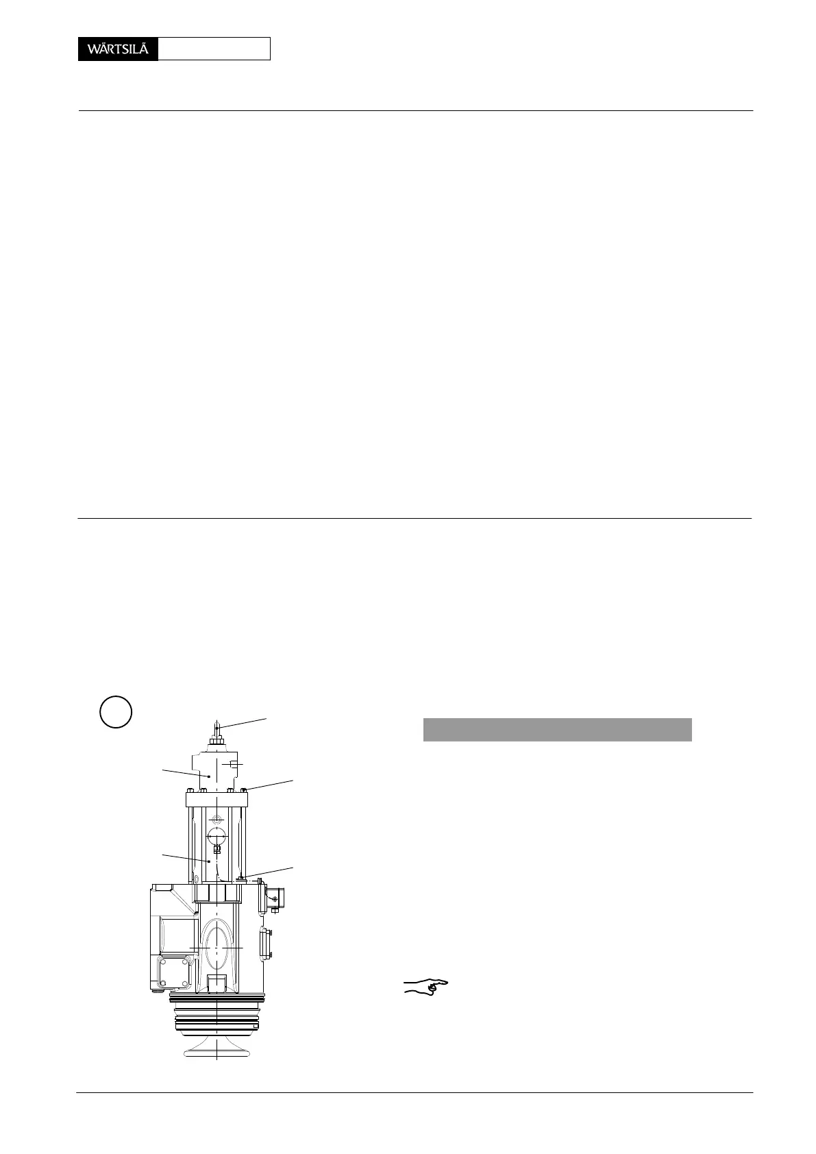
Tools: Key to Illustrations:
1 Depth gauge 94126 1 Valve cage 21 Guide bush
1 Pressure element 94259a 2 Lower housing 22 Rod seal ring
1 Torque wrench 3 Nut 23 Valve seat
4 Screw 24 Screw plug
5 Upper housing 25 Filter with orifice
6 Outside piston 26 Adapter
7 Inside piston 27 Non-return valve
8 Thrust piece 28 Throttle screw
9 Valve spindle 29 Spring dowel pin
10 Measuring cone 30 Valve stroke sensor
11 Piston guide 31 Screw
12 Spring dowel pin 32 Housing
13 Screw with washer 33 Damper
14 Circlip 34 Shim
15 Valve cotter 35−42 O-rings
16 Piston
17 Piston seal ring BO Bore
18 Disc spring HH Hydr. HP pipe
19 Distance ring OB Oil bore
20 Head screw RC Eye bolt
Overview
1. General 1/9...............................................
2 Dismantling of exhaust valve 3/9...........................
3. Assembling of exhaust valve 5/9...........................
4. Blocking of exhaust valve 9/9..............................
A
1. General
There are in minimum two complete exhau
valves on board, as recommended by the Intern
tional Association of Classification Societie
(IACS). Therefore, they must be used as a r
placement in any case of difficulties appeare
during operation.
Defective exhaust valves may, however, only b
repaired or reconditioned by qualified personn
or a Wärtsilä Switzerland Ltd. authorized repa
workshop.
For inspection and overhaul intervals see Maint
nance Schedule 0380−1.
Remark: Pay attention to General Guidelines f
Lifting Tools 0012−1.
RC
3
013.145/05
4
2
5
xhaust Valve
ismantling and Assembling
2011-12