Maintenance
2745−1/A1
RT-flex50-D
Wärtsilä Switzerland Ltd
1/ 2
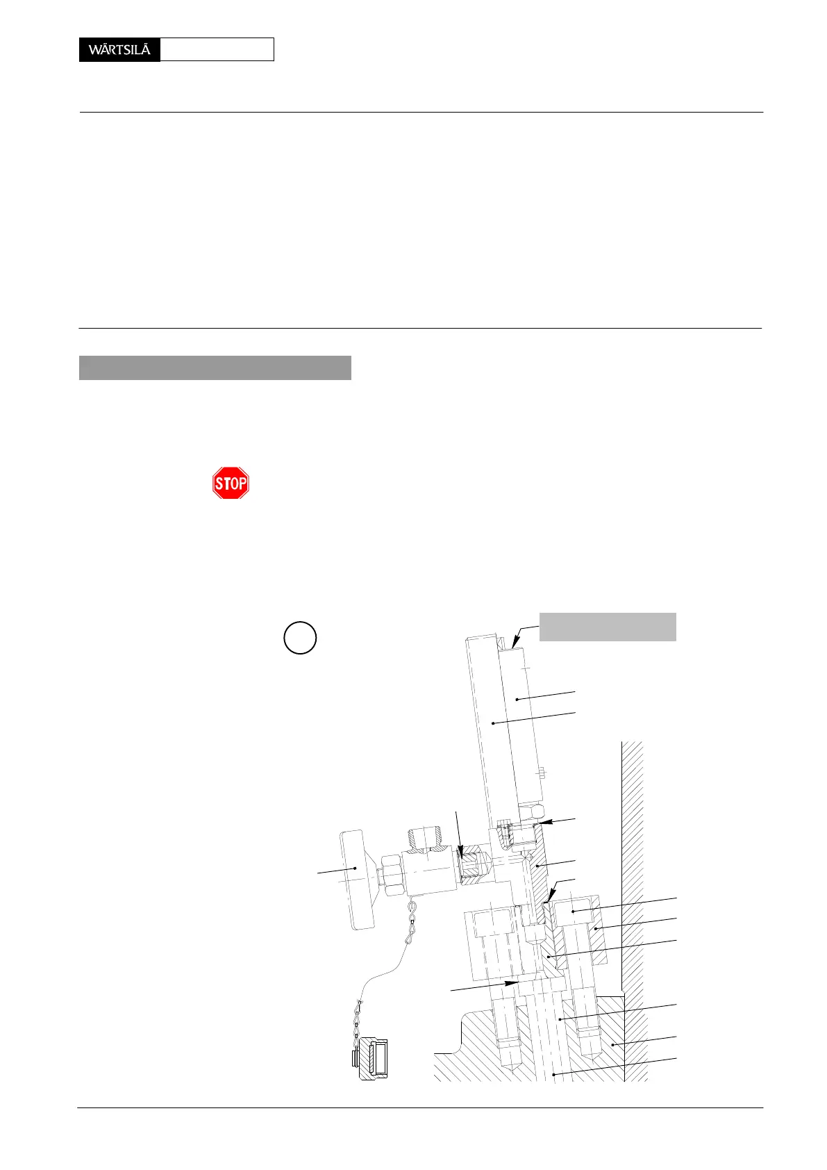
Tools: Key to Illustrations:
1 OBEL test bench 94272 1 Cylinder cover 10 Receiver
1 Valve holder 94272c 2 Relief valve 11 Gasket
1 HP oil pump 94931 3 Indicator valve 12 Gasket
2 Hydr. distributors 94934a 4 Adapter piece
1 HP hose 94935 5 Protection plate
6 Flange EV Relief valve
7 Adapter MD Metallic sealing
8 Sleeve RB Relief bore from
9 Allen screw compression chamber
1. General
Each cylinder cover is provided with an indicator valve combined, depending on
Class requirements, with a relief valve, which is connected by relief bore ’RB’ to the
compression chamber. An inadmissible high pressure peak in the compression
chamber opens the valve and the over-pressure is immediately reduced.
A relief valve which has blown off or valves leaking during engine operation
must be replaced at the first opportunity (with engine stopped only).
A relief valve can not be repaired nor adjusted any more after having blown-
off!
Relief valves require no maintenance, however they should be checked in general
at every major engine overhaul. Basically leaking or damaged valves should be
returned to the manufacturer for inspection and repair.
A
017.671/08
2
3
5
11
4
12
12
MD
BLOW-OFF PRESSURE
STAMPED IN
9
6
7
8
1
RB
elief Valve for Cylinder Cover
hecking Blow-off Pressure
2010