Maintenance
8447−1/A1
RT-flex50-D
Wärtsilä Switzerland Ltd
1/ 4
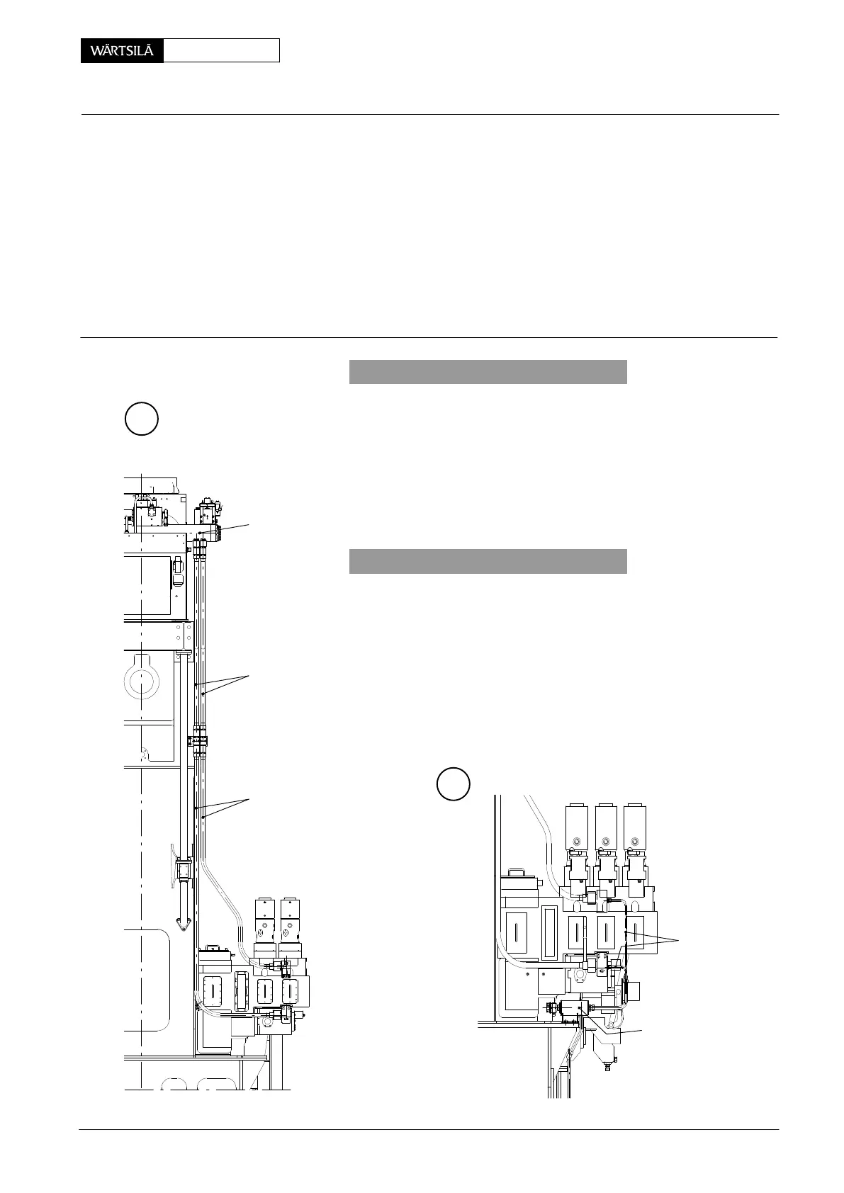
Tools: Key to Illustrations:
1 Regrinding device 94834 1 Servo oil rail 10 Thrust ring
2 Servo oil piping 11 Non-return valve
3 Servo oil piping 12 Leakage oil pipe
4,a,b Screw 13 Oil leakage monitoring
5,a Flange 14 Connecting block
6 Screw 15−17 O-ring
7 Intermediate piece
8 Non-return valve DF Sealing face
9 Claw OE Oil inlet
A
1
2
013.511/05
1. General
The engine must be stopped and then the servo oil pipings ca
be drained via leakage oil pipes 12, however, also a tray shou
be placed under the connecting blocks.
D For that screws 4a must be loosened and flange 5a, resp.
and 5 at connecting block 14 pushed back in order to sep
rate servo oil piping from its sealing faces ’DF’.
Non-return valves 11 prevents servo oil rail from discharging
2. Removal
D Depending on the servo oil piping to be removed, the pi
ing from servo oil service pump 4.88 to oil inlet ’OE’ (Fi
’C’) must also be removed.
D To remove servo oil piping 2, the relevant servo oil piping
must be removed first.
D Pay attention not to damage sealing faces ’DF’.
D All connections must be closed off immediately and th
sealing faces must be protected against any damages.
12
13
B
3
ervo Oil Piping
emoving, Fitting and Regrinding
2010