Maintenance
6708−1/A1
RT-flex50-D
Wärtsilä Switzerland Ltd
1/ 10
Tools: Key to Illustrations:
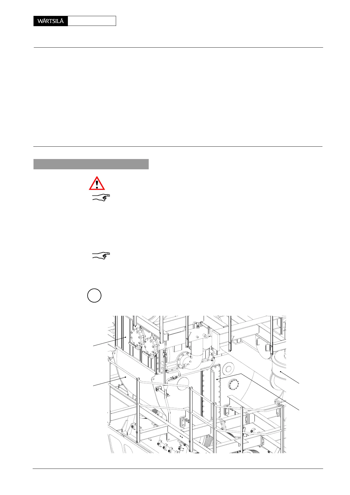
1 Lifting and withdrawing gear 94667 1 Receiver (underslung) 11 Frame
1 Withdrawing gear 94667a 2 Scavenge air cooler 12 Rail
1 Lifting tool 94667b 3 Water separator 13 Round rubber cord
1 Bracket 94667c 4 Auxiliary blower 14 Round rubber cord
1 Limiter (for one SAC) 94667d 5 Cover
1 Limiter (for two SACs) 94667e 6 Guide bar
1 Holder 94667f 7 Intermediate ring DP Depository
8 Screw M16x55 H
1
, H
2
Trolley with spur-
9 Screw M6x12 geared chain block
10 Rod ∅6 mm H
3
Manual ratchet
1. Preparation
Risk of accident! Immediately close the openings off after removing the bottom
plates!
Remark: Pay attention to General Guidelines for Lifting Tools 0012−1.
D Remove the platform, support and the corresponding bottom plates which
hinder the removal of the water separator.
⇒ Remove cover 5 (60 kg) from receiver 1.
⇒ Loosen and remove all screws 8 (18 pieces) together with their intermediate
rings 7 (Fig. ’B’).
Remark: Keep after using all special screws and devices at the proper deposito-
ries ’DP’ provided on tools 94667, 94667a, 94667b, 94667c, 94667d, 94667e and
94667f (see also 9403−5).
018.312/09
A
4
2
5
1
ater Separator
emoval and Fitting of Water Separator
2010