Maintenance
9223−1/A1
RT-flex50-D
Wärtsilä Switzerland Ltd
9/ 22
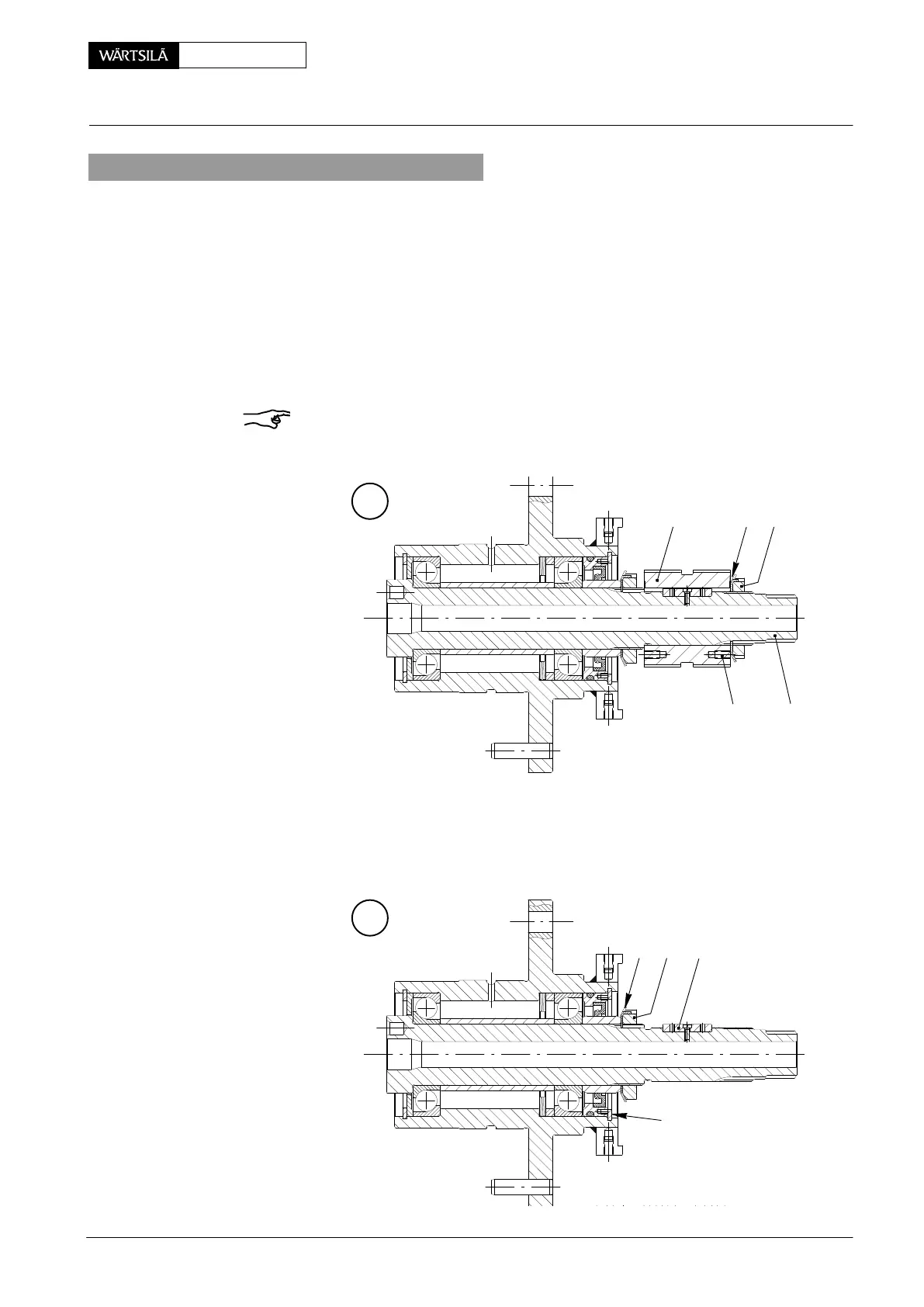
5. Dismantling the crank angle sensor drive
Recommendation: To ensure a high availability and quality standard we recom-
mend that a complete crank angle sensor drive according to Fig. ’K’, view II (in-
cluding shaft encoder Fig. ’D’) always be kept in stock. Maintenance works as de-
scribed in sections 5 and 6 may be carried out only by qualified manufacturers as a
matter of principle.
⇒ Remove shaft encoder according to paragraphs 1.2 and 1.3.
⇒ Unbend locking plate 24, loosen and remove shaft nut 25 using hook spanner
94924.
⇒ Withdraw gear wheel 18 from the shaft 5.
Remark: If withdrawing by hand is not possible, the gear wheel must be removed
by means of the two tap holes ’GL’ and suitable tools, however, without striking and
damaging the toothing.
L
18 2524
5
GL
⇒ Remove circlip 28 using a snap ring tong.
⇒ Unbend locking plate 26, loosen and remove shaft nut 27 using hook spanner
94925.
⇒ Remove shaft 5, however, key 38 remains in situ.
M
38
28
27
26
2011
rank Angle Sensor Unit: Dismantling, Assembling and Adjusting