Maintenance
3303−1/A1
RT-flex50-D
Wärtsilä Switzerland Ltd
5/ 5
5. Tensioning the stud of top end bearing
Remark: For tensioning the studs always follow the sequence shown in Fig. ’D’
i.e. a+a and b+b for each step.
⇒ Clean the threads of studs 1 as well as the area around nuts 2.
⇒ Apply oil to the stud threads and screw on the nuts.
⇒ Tighten the nuts with round bar ’RS’ and equally distribute clearance ’y’ be-
tween the bearing halves (bearing protrusion) as shown in Fig. ’D’.
⇒ Open vent screw 7.
⇒ Place pre-tensioning jacks 94315 diagonally onto studs as shown in Fig. ’D’,
and completely screw them on until there is only little or no clearance at ’x’
(Fig. ’F’).
⇒ Connect the pre-tensioning jacks to hydraulic unit 94942 as shown in Fig. ’D’.
⇒ Actuate the hydraulic unit till bubble-free oil flows out through the vent screws.
Close vent screws.
⇒ Actuate the hydraulic unit and set pressure to 1000 bar (1
st
step) and keep
pressure constant.
Pistons 8 of the pre-tensioning jacks must never exceed the red limiting grooves
’BN’ (Fig. ’F’).
Tighten the nuts with round bar ’RS’ and check with the feeler gauge through slot
’KO’ (Fig. ’F’) that no clearance remains between nut and supporting surface.
Check with the feeler gauge that no clearance remains between bearing cover and
connecting rod.
(Should clearance remain, loosen the fastening and compare the bearing protru-
sion with the nominal value as indicated in 3303−3).
⇒ Proceed in the same manner for the second pair
the connecting rod studs.
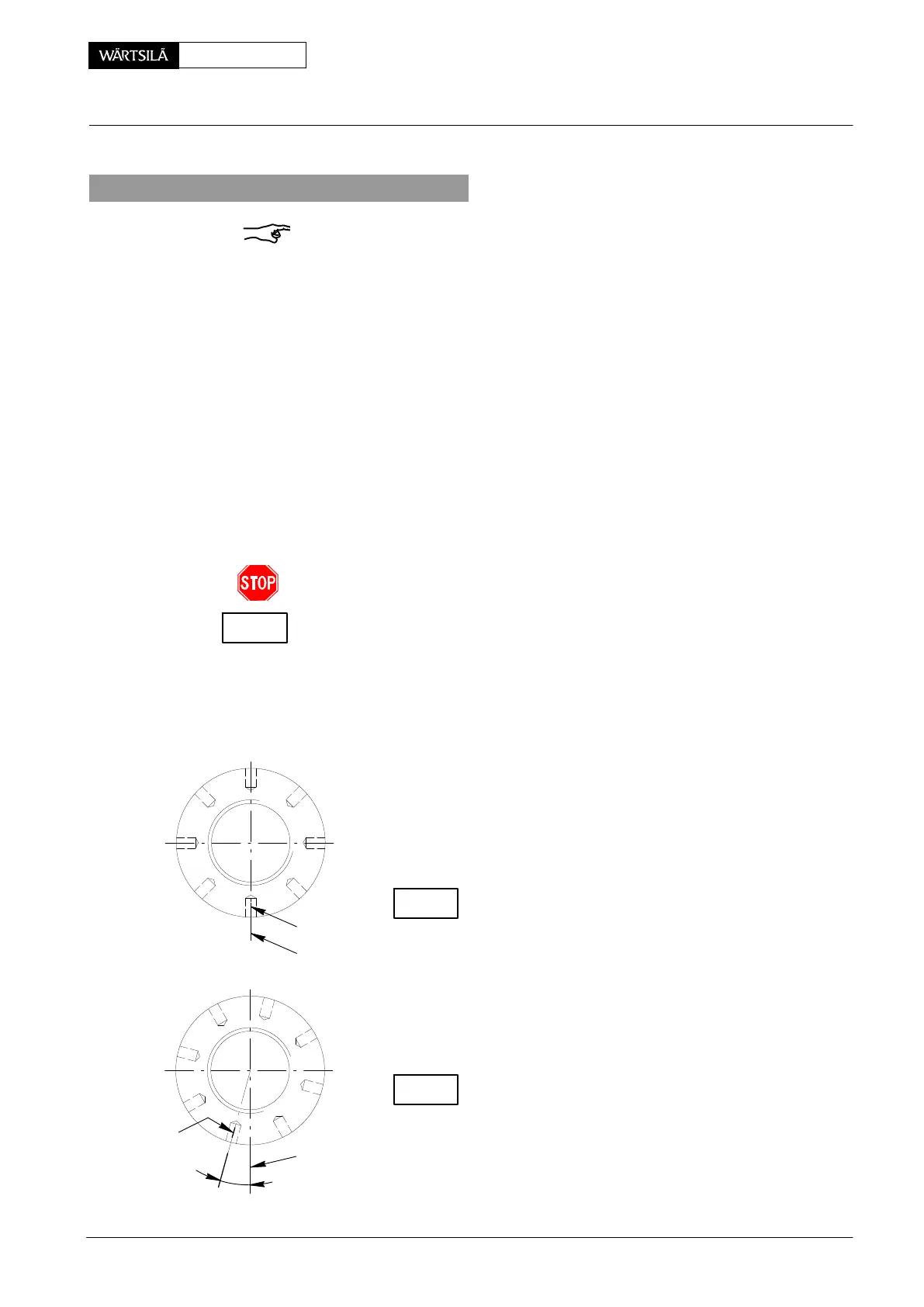
⇒ After tensioning to the 1
st
step mark the position
the nuts against bearing cover as shown in Fig. ’a
⇒ Raise the pressure to 1500 bar (2
nd
step) and kee
constant.
Tighten nuts down and check correct seating with th
feeler gauge.
Check from the markings applied by how much the nu
were turned after pre-tightening (1
st
step).
Tightening angle to be about 15_ (Fig. ’b’).
Should considerable differences to these nominal va
ues be encountered then repeat the tensioning proces
⇒ Release pressure to ’0’ at the hydraulic unit and r
move pre-tensioning jacks.
Finally check the vertical bearing clearance (see Clea
ance Table 0330−1 ’Top and bottom end bearings to co
necting rod’).
CHECK
CHECK
TIGHTENING
ANGLE
Fig. ’a’
Fig. ’b’
x
013.432/05
y
x
009.758/02
y
Loosening and Tensioning the Connecting Rod Studs
2010
CHECK