Maintenance4103−1/A1 RT-flex50-D
Wärtsilä Switzerland Ltd
2/ 2
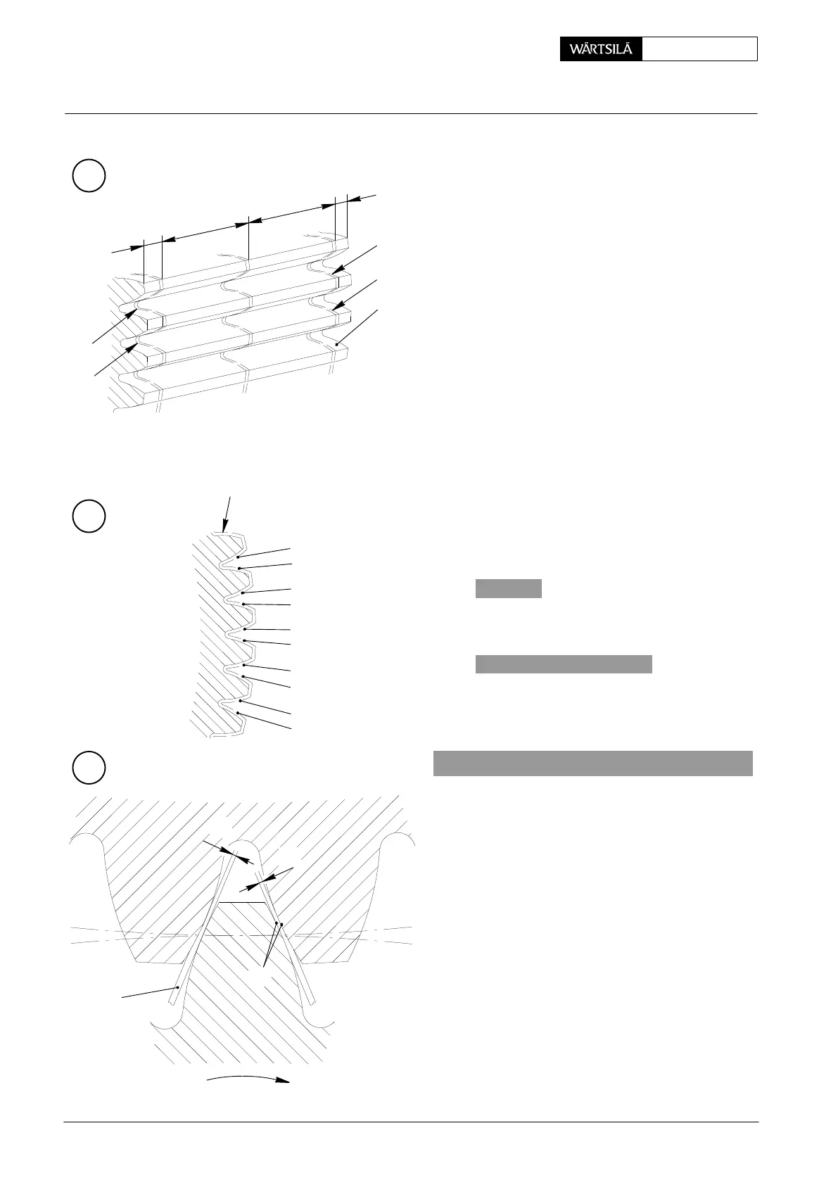
3.3 Measuring tooth backlash with lead wire
D Use a fresh piece of lead wire Pb 99.9 fine
1.5 mm diameter for each measurement.
D Always use lead wires of the same diamet
and quality.
⇒ Place lead wire pieces a, b, c of about 200 m
length around the tooth profile and attac
them with scotch tape (see Fig. ’A’ and ’B’)
⇒ Number the tooth profiles in accordance wi
Fig. ’B’.
⇒ Turn the lead wires only once through th
teeth meshing.
D Lead wire ’c’ (Fig. ’A’) serves to verify tot
tooth backlash ’f’ (Fig. ’C’).
With lead wires ’a’ and ’b’ (Fig. ’A’) the too
profile parallelity is checked.
D Total tooth backlash ’f’ (Fig. ’C’) composes
f
1
and f
2
(thickness of lead wire):
f = f
1
+ f
2
D Obliquity ’Df’ is calculated from the differenc
in thickness of the squashed lead wires alon
driving flanks TF (Fig. ’A’):
Df = a
1
− b
1
or a
3
− b
3
etc.
D The admissible deviation of tooth profile p
rallelity amounts to max. 0.2
o
/
oo
across th
width of the tooth.
4. Checking the running performance
To enable judging the running performance
the gear train after recommissioning, thre
teeth each of the gear wheels are smeare
with a thin coat of oil resisting marking blu
(ink) equally spread. This check is necessa
in order to verify the mating appearance of th
teeth.
One brand of oil resisting marking blue is, f
example, Dykem Layout Red Dx-296.
LEAD WIRE Ø 1,5 mm
a
1
a
3
7
a
c
b
0
1
2
3
4
5
6
...
...
...
TF
c
A
B
C
15 mm
15 mm
=
=
b
1
b
3
f
1
f
2
000.653/93
000.653/93
000.653/93
Checking the Running and Backlash Clearances and Condition of Teeth
2010