Maintenance
5801−1/A2
RT-flex50-D
Wärtsilä Switzerland Ltd
1/ 2
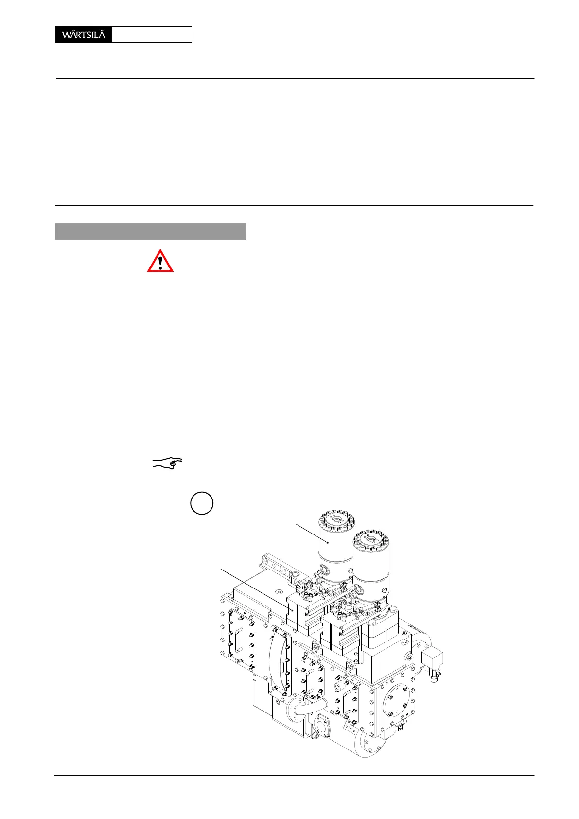
Tools: Key to Illustrations:
2 Spacers 94555a 1 Fuel pump 8 Connecting element
2 Actuator 9 Toothed rack
3 Output shaft 10 Set screw
4 Damper 11 Self-locking nut
5 Lever 12 Spot-face
6 Clamping sleeve
7 Screw MA Mark
1. General
Attention! The power to the actuator must be interrupted before disconnecting it
from the connecting element (see 9362−1 in the Operating Manual).
After overhauling or fitting a new fuel pump or an actuator according to manufactu-
rer’s instructions, the adjustment of the linkage must be checked and the following
points observed:
D Connecting element 8 and damper 4 (retracted: ’x’ = 190 mm or extended: ’x’
= 240 mm) freely movable and part concerned lubricated with MOLYKOTE
paste G.
⇒ Mark lever position to output shaft with slight center punch strokes ’MA’.
⇒ Center output shaft 3 manually (set point).
⇒ Position lever 5 parallel (view I) with its clamping sleeve 6.
⇒ Center toothed rack, i.e. adjust it to 36 mm on both sides using spacers
94555a.
D Always join lever and regulating rack with connecting element (spot face 12
pointing to lever 5) by means of set screws 8 in good condition and tightened
with their self-locking nuts 11.
Remark: In case of an emergency, i.e. for operation with defective actuator(s) see
0515−1 in the Operating Manual.
A
WCH00245
1
2
egulating Linkage
djusting with Woodward ProAct II − Analog Actuato
2011