Maintenance2751−2/A1 RT-flex50-D
Wärtsilä Switzerland Ltd
6/ 9
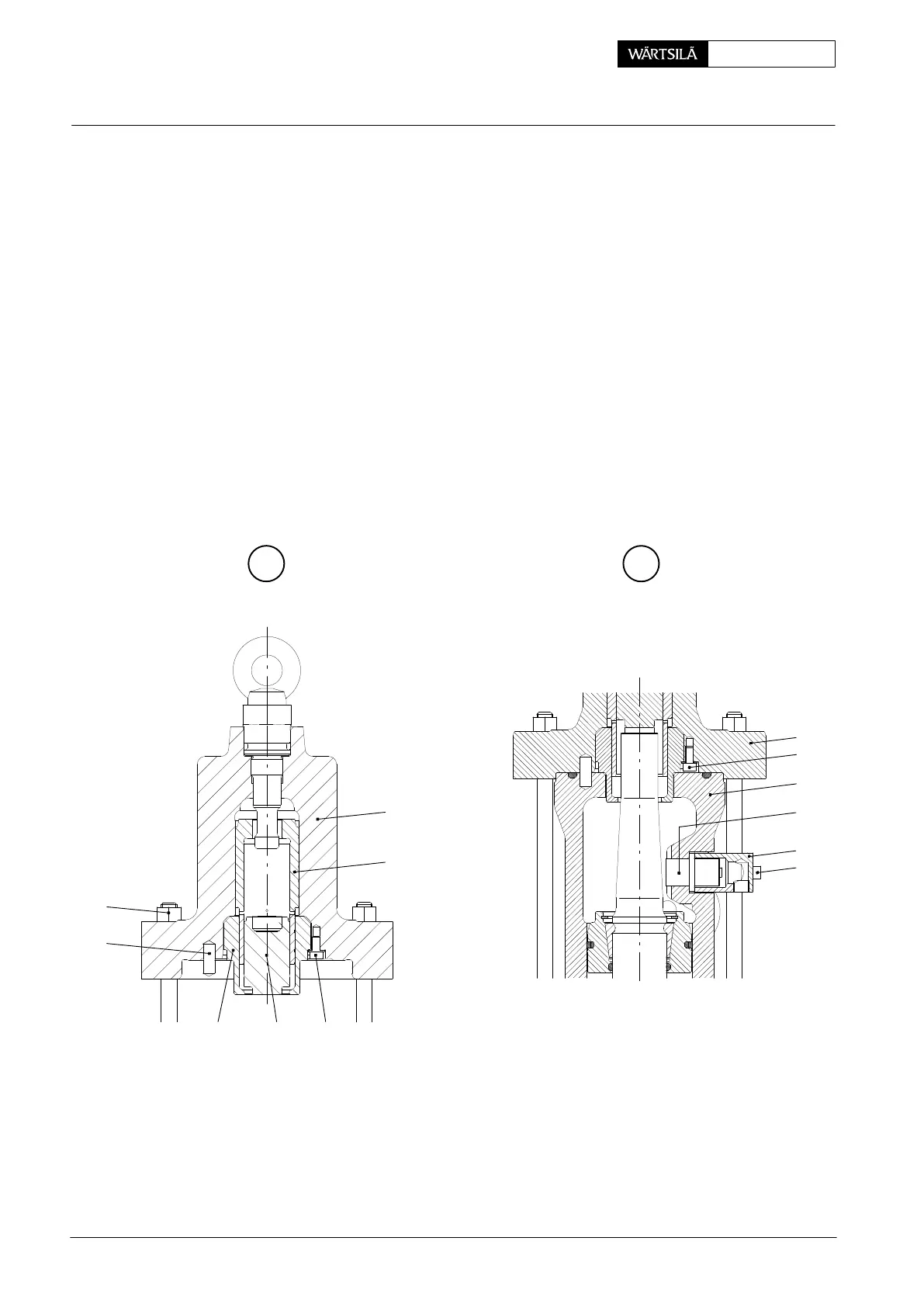
3.2 Assembling of valve drive
⇒ Bring valve cage to vertical position and fit disc springs 18 as shown in Fig. ’C’.
⇒ Fit piston 16, valve cotters 15 and circlip 14.
⇒ Fit lower housing 2.
⇒ Fit and tighten screws 4 (Fig. ’A’).
⇒ Fit upper part of valve drive paying attention to position of spring dowel pin 12
(Fig. ’F’).
⇒ Oil nuts 3, fit and tighten them equally up to a torque of 125 Nm.
3.3 Fitting of valve stroke sensor
⇒ Clean valve stroke sensor, bore and collar in lower housing as well as trans-
mitter housing.
⇒ Push valve stroke sensor 30 together with transmitter housing 32 into the bore
and fasten it using screws 31.
G
WCH00406
3
12
13
5
31
32
30
2
F
016.601/08
11 137
5
6
2011-12
xhaust Valve: Dismantling and Assembling