Maintenance
3303−3/A1
RT-flex50-D
Wärtsilä Switzerland Ltd
5/ 6
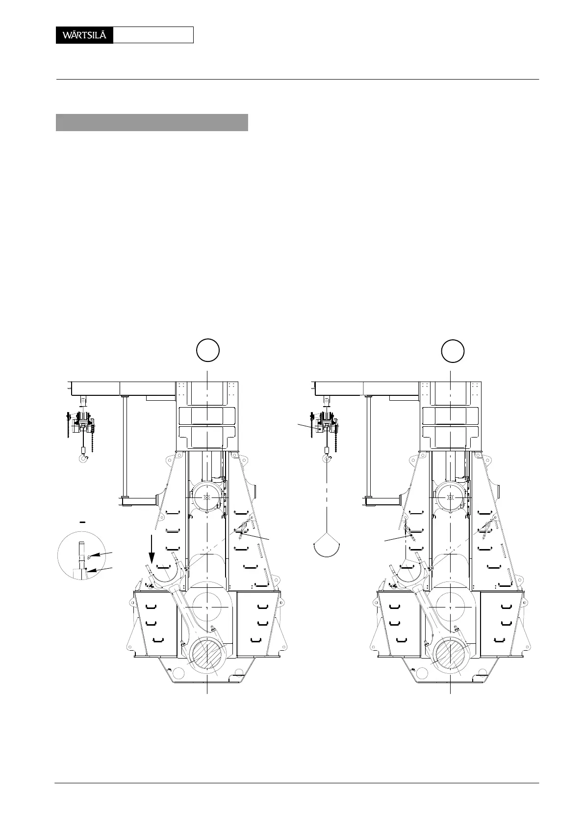
2. Removal of bearing shell
⇒ Swing the connecting rod with lifting tackles H
1
and H
2
(Fig. ’A’) to fuel side,
ensuring that it will not tilt back to exhaust side.
⇒ Remove lifting tackle H
2
and swing connecting rod to the position as shown in
Fig. ’E’.
⇒ Remove Allen screw 10 for positioning bearing shell 11.
⇒ Fit eye bolts M6 into the front faces of the bearing shell and connect these with
rope ’c’ as shown in Fig. ’F’.
⇒ Remove the bearing shell with rope ’c’ and lifting tackle H
3
.
⇒ Lift the bearing shell out of the connecting rod whereby the threads of the con-
necting rod studs must be covered with lugs in order not to damage the bea-
ring shell.
H
1
E
F
11
013.632/05 013.637/05
10
I
13
H
3
c
c
I
2010
Inspection, Removal and Fitting of Top End Bearing