Maintenance
3403−2/A1
RT-flex50-D
Wärtsilä Switzerland Ltd
1/ 2
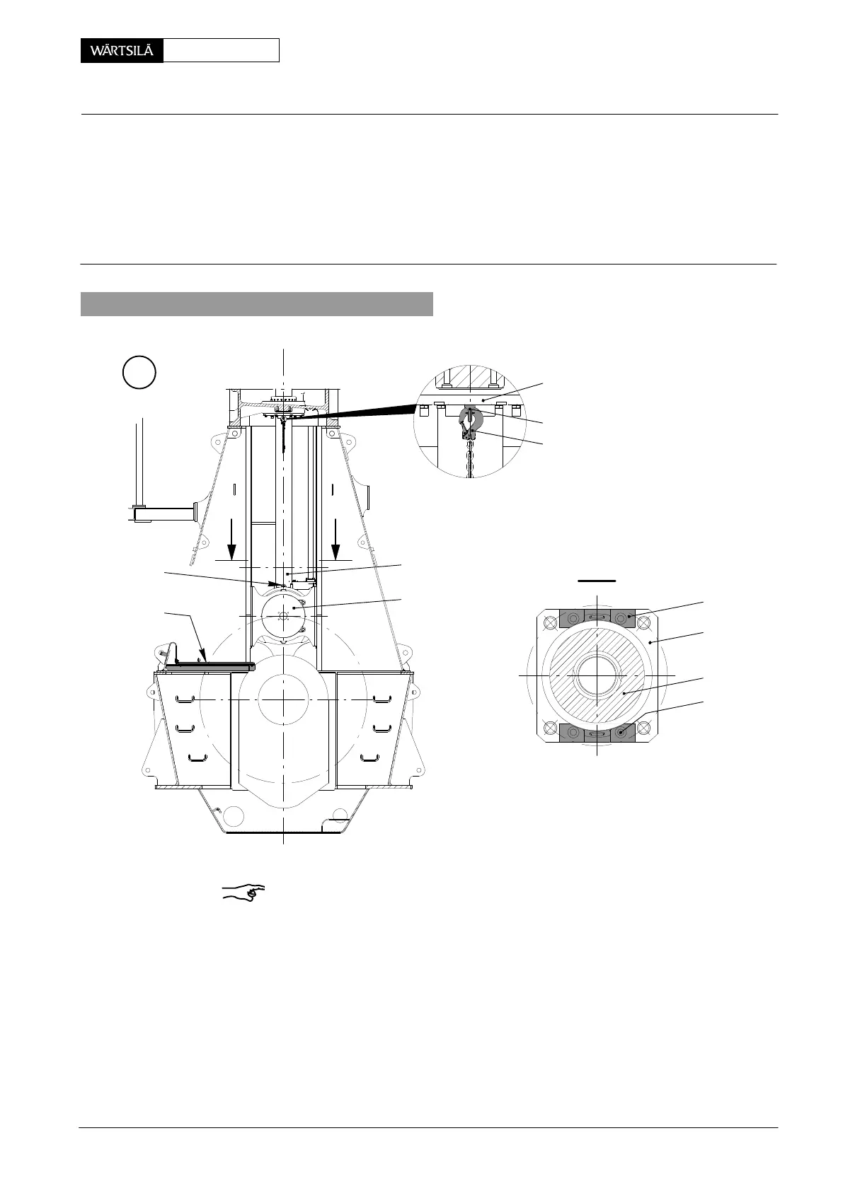
Tools: Key to Illustrations:
1 Working platform 94142 1 Piston rod gland support 6 Compression shim
2 Lifting bosses 94333a 2 Piston rod 7 Waisted stud
2 Suspension chains 94333b 3 Piston rod foot 8 Dowel pin
4 Crosshead pin
5 Allen screw RC RUD-eye bolt
1. Fitting and removing compression shim
A
I - I
013.552/05
013.553/05
1
RC
94333b
94333a
94142
94333a
3
2
5
I
I
4
2
Remark: Pay attention to:
− General Guidelines for Lifting Tools 0012−1.
− Utilization of Working Platform 3301−1.
⇒ Turn crank of the cylinder concerned to B.D.C.
⇒ Install working platform 94142 according to the instruction in 3301−1.
⇒ Loosen the nuts of the waisted studs for the screwing of piston rod foot 3 and
crosshead pin 4, as described in 3403−1.
⇒ Fasten lifting bosses 94333a with their Allen screws 5 on the piston rod foot.
⇒ Screw two RUD-eye bolts ’RC’ into piston rod gland support 1 and hang both
suspension chains 94333b on them as shown in Fig. ’A’.
⇒ Remove the working platform.
iston
hanging the Compression Shims
2010