Maintenance3403−2/A1 RT-flex50-D
Wärtsilä Switzerland Ltd
2/ 2
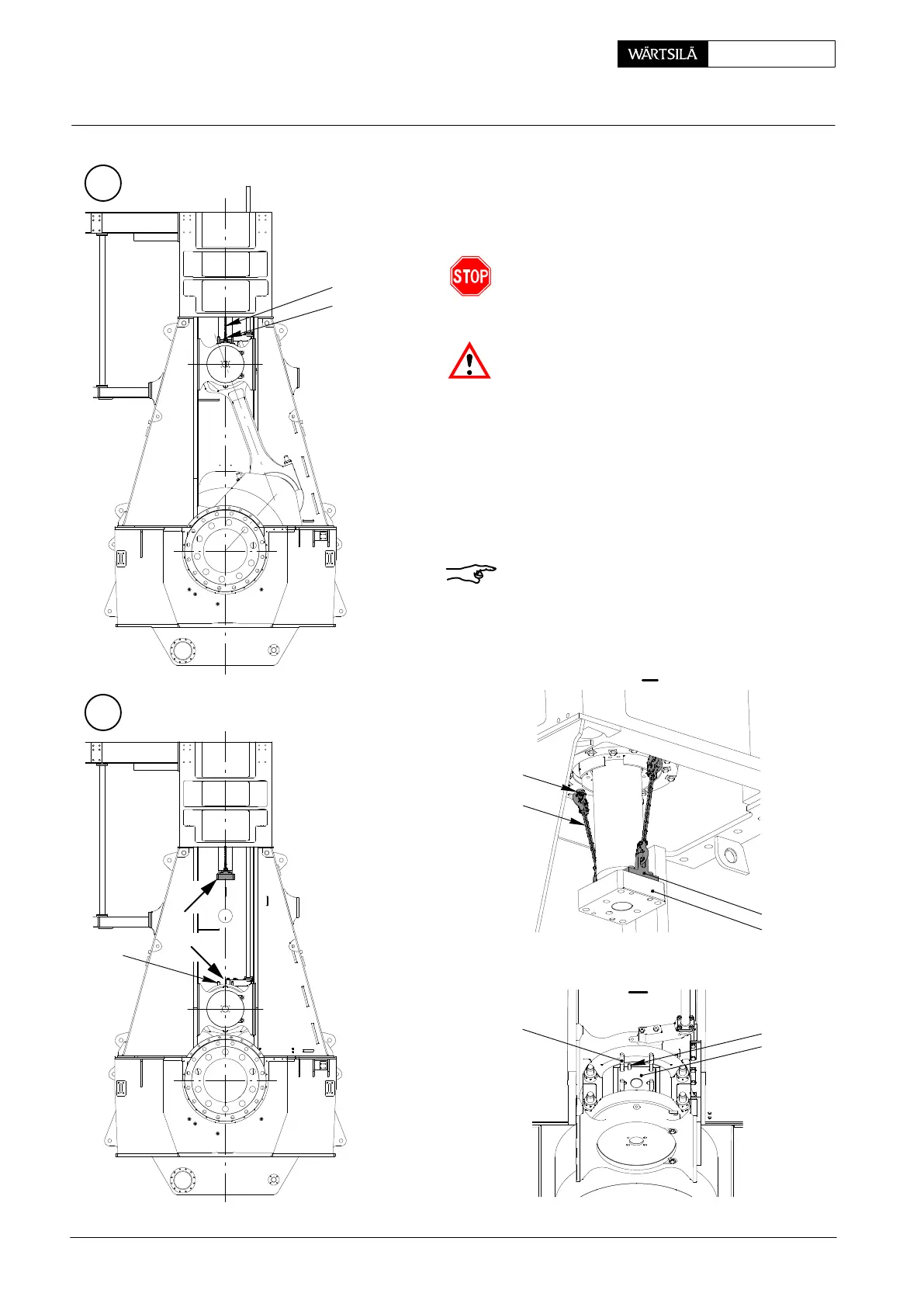
⇒ Turn crank upwards to exhaust side unt
suspension chains 94333b can be put int
lifting bosses 94333a as shown in Fig. ’B’
The crank may be turned max. 30_ toward
T.D.C.
Pay attention to the warning plate provided o
the holders!
Carefully turn crank downwards until waiste
studs 7 are out of piston rod foot 3 (Fig. ’C’).
Take care that the two dowel pins 8 in crosshea
pin 4 do not jam in the piston rod foot.
⇒ Loosen and remove the screws fastenin
compression shim 6.
⇒ Remove the compression shim with the ai
of two eye bolts.
For fitting a new compression shim proceed i
reverse sequence to the removal.
Remark: Please note the correlation betwee
setting screw ’ST’ on measuring gauge 9422
(see 2124−1) and the mean thickness of built-i
compression shims.
B
C
013.691/05
013.692/05
013.693/05
7
RC
94333b
94333a
I
II
7
94333b
94333a
3
8
6
I
II
iston: Changing the Compression Shims
2010