Maintenance
5556−1/A1
RT-flex50-D
Wärtsilä Switzerland Ltd
7/ 9
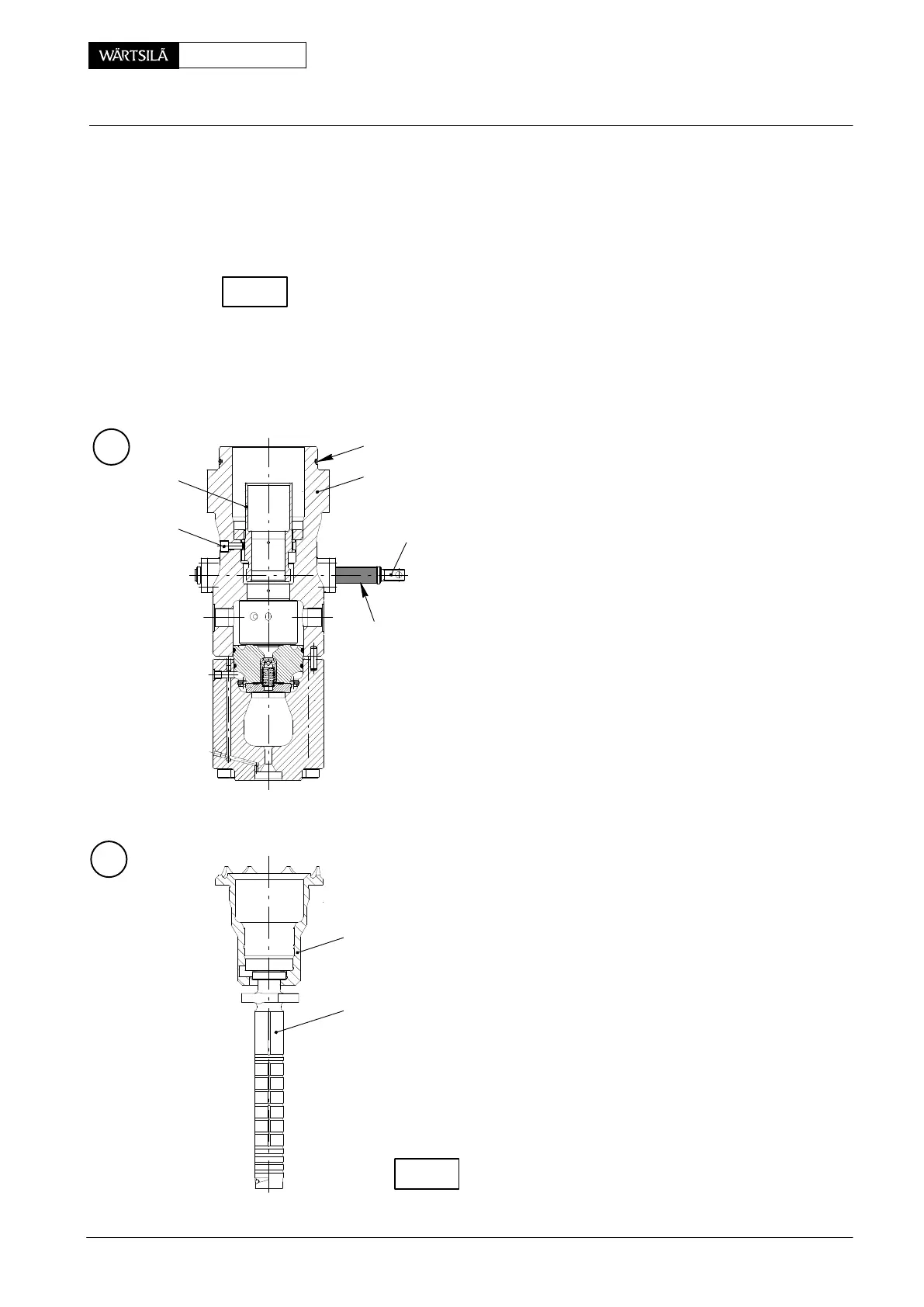
4.4 Fitting the regulating rack
⇒ With the pump cover turned towards the bottom, fasten the upper housing
onto a work bench.
⇒ Fit regulating rack 25 according to Fig. ’H’.
Check regulating rack 25 for easy movement.
⇒ Place rod seal ring 38 in both flanges 24.
⇒ Push both flanges onto the regulating rack and screw them up with the upper
housing.
⇒ Fit stop rings 27 and circlips 26.
L
20
21
25
94555
013.680/05
4.5 Fitting the regulating sleeve
⇒ Bring regulating rack 25 to position shown in Fig.
and place spacer 94555.
⇒ Fit regulating sleeve 21 in the upper housing, th
toothed rim turned to the bottom and the groove
12 mm width being flush with guide pin 20.
5
40
4.6 Fitting the pump plunger and lower housing
⇒ Fit upper spring carrier 22 and compression sprin
19 (Fig. ’G’).
⇒ Nest pump plunger 18 in lower spring carrier 17.
⇒ Lubricate the pump plunger with clean diesel o
and insert it in pump cylinder 33, taking care th
both drivers at the pump plunger mesh in the lead
regulating sleeve 21 (Fig. ’G’).
⇒ Place O-ring 40 in upper housing 5 and lubricate
(Fig. ’L’).
⇒ Tension the lower and the upper housing togeth
by means of two Allen screws 16. Thereby spring 1
is compressed (Fig. ’F’).
After screwing up both housings with each other, chec
regulating rack 25 for easy movement.
M
17
18
008.656/00
CHECK
2010
uel Pump: Dismantling and Assembling
CHECK