Maintenance
5612−1/A1
RT-flex50-D
Wärtsilä Switzerland Ltd
1/ 3
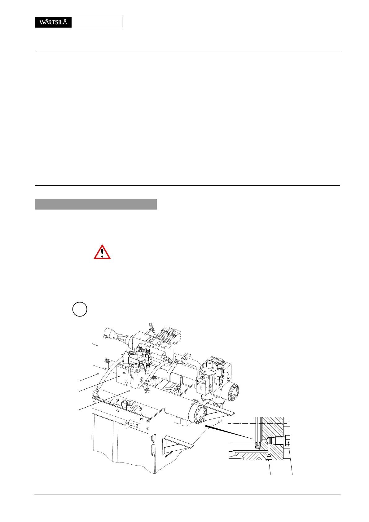
Key to Illustrations:
1 Servo oil rail 15 Filter holder
2 Drain screw 16 Seal
3 Screw plug 17 Circlip
4 Valve control block 18 Oil filter
5 Allen screw M16x160 19 Orifice
6 Piston 20 Rail valve (pre-control valve)
7 Sealing flange 21 Allen screw M4x16
8 O-ring & back-up ring 22 Return pipe
9 Pan head screw M5 23 Dowel pin
10 Cover 24...26 O-rings
11 Allen screw M10x40
12 Compression spring
13 Slide rod RC Eye bolt
14 Screw plug with seal AF Seating surface
1. General
The piston and slide rod should be checked at random according to Maintenance
Schedule 0380−1.
When working on the exhaust valve control unit the engine has to be stopped.
Attention! Servo oil pipings must be pressureless and properly drained by means
of carefully opening drain screw 2 and screw plug 3.
Follow the instruction in 0520−1 of the Operating Manual without fail!
The respective work station must be clean; welding and grinding should not be
done nearby!
TO EXHAUST VALVE
SEE 8460−1
A
2
1
22
3
4
WCH00694
xhaust Valve Control Unit
emoval, Fitting, Dismantling and Assembling
2011-12